In the summer of 2011,
I acquired a Stancor 10P transmitter in complete-but-modified condition. Lately, it's been bothering me that I don't have an HF, AM ham transmitter that works, despite owning three of them and having a long-standing breadboard project to build another.
The 10P looked like a good place to start. It's the smallest of the lot, doesn't run a lot of power, and uses standard tubes.
A closer look under the chassis revealed extensive mods -- the 6J5 oscillator tube replaced by a 6AG7 (which would provide more than plenty of drive for the poor 6L6 PA!), the 80 rectifier replaced by a 5Y3,* five-pin crystal socket swapped for an octal, extra components, and a rather casual attitude towards things like making good soldered joints, lead dress, and similar items. Much of the wiring was old and the newer stuff was a bit, well, sub-optimum.
It seemed best to clear it all away and start over. I'm about half done.
The bigger holes in the back of the chassis were for an SO-239 socket (replacing one of the two ceramic feedthroughs for RF output) and a pair of feedthrough capacitors on the incoming AC line. I'll have to make some small plates to hold a replacement RF output feedthrough and the line-cord grommet and a fuse (probably a 5x20mm "Eurofuse," as the holders are tiny. It's not period but it's a minimal change.)
It should look like this:
Comparing the two, it appears the original builder of mine didn't have a hot enough iron to tack ground connections directly to the chassis (but tried anyway), and later on, bolted-in ground lugs were added. My smaller American Beauty iron
can solder to the chassis -- there's a test spot over to the left in the upper photo, near the 5-pin coil socket.
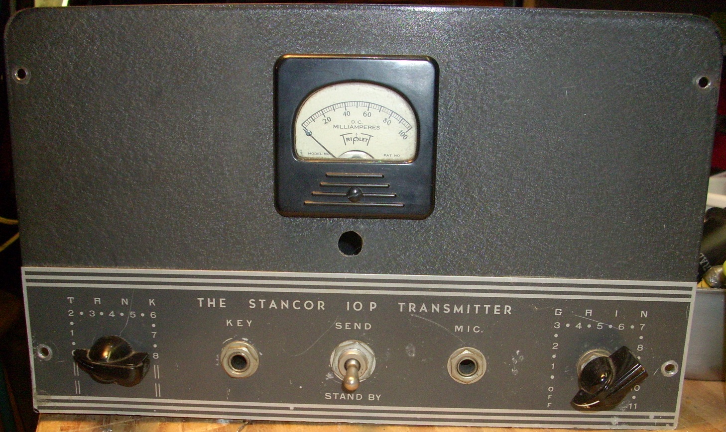
Here's the front panel.
The hole below the meter was for a B+ test point, which I have removed. A hole plug will fill it; I could patch the panel but matching the original paint color would be almost impossible. I'll polish the control-label plate, which will help minimize the scratches.
It's
small. Scale may be a little hard to grasp -- the "Key" and "Mic." jacks are standard 1/4" types.
For completeness, here's a top view.
I'll try to post updates as the work continues. Ohmmeter checks of the power transformer have me hopeful it's still good.
_____________________________________________________
* I'll probably keep the 5Y3. Essentially an octal-base twin to the '80, they're a bit more affordable and easier to find.


You've got your work cut out for you!
ReplyDeleteNice piece to work on and I like your plan. Looks like a steel chassis and with the big transformer, it must weigh a ton. When it finally gets fired up again, the smell of hot glass, steel and rosin flux will be heady!
ReplyDeleteAre you going to try and reform those Sprague Atoms, or just replace them?
ReplyDeleteThey're replacements and a user-mod (in series, with equalization resistors), so they're not going back in. I have a couple of options for replacement.
ReplyDeleteHoping to re-use the potentiometer, the variable capacitor, the jacks and the RFC, along with the meter, all the iron and most of the tube sockets. The rest will get new parts.
I know you're trying to stay close to stock cosmetically, but that hole below the meter would make a nice place to put an "on air" light.
ReplyDeleteI'm not familiar with that transmitter. What's the final input power?
About 13 Watts. Not a lot but not terrible.
ReplyDelete13 Watts will talk along way. About 6 Watts actual average AM output from a 6L6G or GT. CW and Class C will theoretically give you 70% efficiency, but 60% is more like real world results. Only a fortunate few in the late 1930's did any better.
ReplyDeleteThose Bakelite Cinch Jones octals make me homesick for when I came from.
Stranger