Showing posts with label RADIO. Show all posts

Sunday, April 5, 2020

BUILDING A 1:1 BALUN

     Having decided I need a 1:1 balun -- a kind of RF transformer, used to connect unbalanced (ground-referenced) equipment to a balanced device (like my G5RV antenna) -- I found a ferrite toroid core that seemed likely, wound two interwoven 12-turn coils of #14 house wire on it (as much as would fit), and looked around for an enclosure.

     I didn't have much, and then I found my collection of old tea canisters.  That worked.
     The coil is sandwiched between two 1/8" Garolite* plates held by brass screws (one headless) into a ceramic insulator; another, shorter insulator is threaded onto one end and fastened to the bottom of the box.  The lower plate has two corners clipped so the wires from that side can get to the terminals.
     There's a trick to working with such thin metal.  You can drill it, but it's risky -- even with a backing, it can catch and tear.  A better bet is to mark hole centers with a sharp awl and use a Roper-Whitney punch,† which will center up on the awl-made dimples.  Careful work with a hand reamer or chassis punch will enlarge the holes if necessary.  Small holes can just be punched with the awl, especially in places the punch won't reach.  (The lid does fit square, when properly seated.)

     My little SWR analyzer says it's not terrible on the 80 meter ham band and not bad on 40 -- the ferrite I used was supposed to be good through 30 MHz, but the match starts getting worse and worse by the 20 meter band.

     Checked it with the RME-45 receiver and Millen "Junior" transmatch and it works okay, slightly better signals with it between the antenna and the matcher.  80 meters was a jumble of noise this afternoon.  Just went down (10:20 p.m.) and turned on the receiver; as I tuned past 3885 kHz, a voice came out of the speaker: "Hello, Bobbi!  C'mon Bobbi..." 

     That got my attention, as you might expect.  I dodged the slow-rate tuning back and forth a little, and he came back on, "[callsign], this is [other callsign], c'mon, Bobby, if you're not there I'll just call CQ, CQ, CQ , this is [other callsign] and remember, people, don't buy coax jumpers, you build your own.  CQ, CQ, from [other callsign], c'mon..."

     So I wasn't hallucinating.  And I was certainly glad I'd made my own coaxial jumpers!

     Next step, rebuilding the transmit/receive switch and moving the DX-60 transmitter over to the new shelves.
_______________________________
* As close to Bakelite as you can get now.  McMaster-Carr stocks it in a variety of sizes and shapes.

† Mine is actually a Whitney-Jensen, an earlier model with a few minor differences.  These useful little devices are widely available used. Plugging the name into a search engine brings up a lot of listings at online auction sites.

Monday, February 15, 2016

T. R. MCELROY'S STREAMLINED TELEGRAPH KEYS

     T. R. McElroy was a blazing fast telegrapher -- any code, any time.  He worked both landline and radiotelegraphy, and set speed records.

     But he was ambitious, too.  In the 1930s, he started manufacturing semiautomatic telegraph keys of his own design, massive, heavy bugs that suited his own style -- and which appealed to plenty of others, too.

     The original Mac bugs were heavy, rectilinear keys with their own style, a little "Arts & Crafts meet heavy industrial" look.  But the times --and the styles -- were changing and shortly before WW II, Mac introduced a series of streamlined telegraph keys unlike any any other, culminating in the S-600 Super Streamspeed semiautomatic key, possibly the most graceful "bug" ever made.

     I own a few Mac keys and recently bought an accessory:
     There's an uncommon Bakelite-based Streamkey at far left, followed by a Telegraph Apparatus Co. (not Inc.) copy* of the wrinkle-finished metal-base Streamkey (you can tell by the bulge in the lever arm at the contact area) and a pair of chrome-plated McElroys.  The Streamspeed is at far right, and it handles just as fast and sleek as it looks.  At the very back, the accessory and its box: an Oscillatone code-practice oscillator.  They are not especially rare and this one was offered at a very low price -- how could I pass it up?

     Restoration will be interesting.  The Bakelite is likely to be very brittle.

     There are still McElroys in the electronics business.  They're not making telegraph keys any more, but the name lives on.
________________________________
* TACo was a co-venture between McElroy and Hallicrafters.  They built copies of Mac Streamkeys and their own interesting semiautomatic key, sometimes known as the "hole-in-the-wall" bug.

Friday, January 15, 2016

A VINTAGE-SUITABLE CALENDAR

     I needed a calendar for my mostly-vintage hamshack.  1932 and 2016 share the same calendar, but buying an old one in intact shape and ripping each month off seemed too destructive to me.

     So I made one.
     The backing sheet is card stock.  The calendar pages look crooked -- the paper fasteners that hold them are a bit loose in the punched holes.  It straightens out when hanging.  The printer output does not look like hand-set type, but might pass for offset printing or lithography.

     I'm trying to figure out how to post the original as a PDF, if any readers would like their own copy.

Sunday, July 12, 2015

INDIANAPOLIS HAMFEST, 2015

     I had to go solo this year, while Tam stayed home to meet the AT&T tech.  This meant, of course, that I lacked even the modicum of restraint she sometimes adds--
     The two large devices are a 1940s Meissner Analyst, which is a kind of "test bench in a box" for receiver servicing, and a 1950s Harvey-Wells Bandmaster, a 25 to 30 Watt AM/CW amateur radio transmitter.  Both appear to be pretty clean; the transmitter needs an external power supply, 400 V at 200 mA.

     Other neat stuff: a pair of vintage binoculars in good shape -- didn't have anything but toy versions, so for $35, why not? -- a very good push drill with straight bits and a "Handyman" Yankee screwdriver, a full set of Birnbach ceramic antenna insulators, chassis-mount octal plugs (good for power supply connections), three General Radio mixer knobs, a couple of Dakaware knobs, a National tube socket and 100 pF variable cap, another 100 pF dual variable capacitor, an SW-3 coil form, a 6F7 tube (possibly for a project) and a pair of 6L7s (used in my microphone mixer).  Plus four 1940s/50s QST magazines, three quartz crystals and and assortment of other nice small parts.  Not shown, a short (10'?) desktop rack and a large toroid core to wind a balun on (you want 'em big -- magnetic saturation is lossy and can produce a lot of heat!).

     I met my dear old friend Don H., and several other people I know slightly, including the talented Jim Borgioli,whose ham work includes building very nice AM transmitters that run at or near the legal power limit. And one ham who knew me!  A young man who'd gone looking for info on the Stancor 10-P transmitter and found my postings about it on Retrotchnologist walked up to me in the flea market area, asked, "Are you Roberta?" and introduced himself.

     Found but missed a nice balanced antenna tuner.  I should have purchased it at first sight!  But it's a cloneable design and I think I have the parts.

     A fun time!  When I returned home, the phone tech was there -- and pointed out a very large broken limb on the roof and my ham antenna and still loosely attached to the tree.  I climbed up and had a look, but it's too big and too precarious for me.  We've called the singing tree hippie, who does great work at a fair price.

Monday, June 1, 2015

CARBON MICROPHONE CHECKING

     I went through most of my collection of carbon mics tonight.  The old ones are nearly always non-working when found: they pick up humidity, the carbon packs solid, and that's it; or the carbon granules dribble out over time. 

     Not all of them.  I found several that still work, and a couple that I'd thought were dead (a Shure Brothers 3-A and a 3-B) aren't.  Here are the working ones:
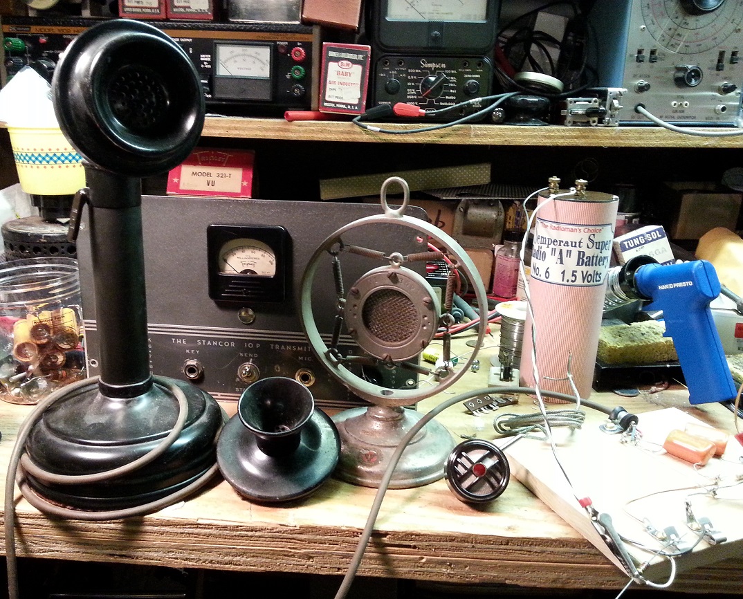
      Two are telephone-types, the T-32 (a pretty common desk mic around WW II) and an odd old telco one from the wood-wall and candlestick era next to it.  The Universal X1 in its nice stand was a complete surprise; I assumed from condition it was a goner.  Nope!  And the little Philmore lapel mic next to it had been sealed up.  The Stancor 10-P -- which needs a carbon mic to do AM -- is behind them.

     Here's my test set-up.  The mic cable goes to a little mixer.  It's isolated with 0.68 uF series condensers, looking at current across a 150 Ohm resistor in series with the mic, a 1.5 V battery and an added resistor to limit current -- I used 820 Ohms and it worked okay for checking.  In practice, you trim microphone current for best fidelity with a carbon -- usually the lower, the better, but there's a point where it stops working.
     Mic cable to mixer at left, connections to carbon mic under test at top right, battery terminals and added current-limiting resistor at bottom right.  I think you can trace it from the photo.

Thursday, March 26, 2015

STANCOR 10P TRANSMITTER: UPDATE 12

     A very long time in coming, I did make progress on the Stancor 10P, getting as far as power supply:

     Rectifier heaters and HV, filter caps, filter choke and bleeder.  It's a little crowded and I struggled to solder the capacitor and resistor to the chassis, even with the big iron.

     That work had it almost done, so tonight I added a few more things:
     Installed output feedthroughs and connected the output, wired up the primary power and the meter.

     Top view:

     Rear view:

     Front view:
     Initial tests -- just power-up, check for excessive current draw, check B+ -- went okay.  Hoping to try more by the weekend.

     Update: Tuned the transmitter up on 40m with a 100 Watt lamp in series, and it made a little power (4:1 balun to a Bird Wattmeter and 50 Ohm load.  Tried it without the lamp and blew the fuse instantly.  So....bigger fuse, and/or 150 and 200W lamps.  Maybe a little Amprobing..

     Update 25 May: Yesterday, I finally brought the transmitter up without a light bulb in series with the 120V AC and it worked. Last time I tried this with the wrong fuse (fast-blow) and it popped immediately -- at which point, I set the transmitter aside for awhile. I didn't have the balun and wattmeter for this test, just a 40W light bulb across the output, which is a bit low-resistance for the link coupling to match to. Plenty more to do but this was a big step.

Thursday, January 29, 2015

YANKEE RADIO TOOL KIT, #106

     Some time ago, I chanced on a nice Yankee No. 100 tool set.  Readers suggested I keep watch for a No. 106 boxed set of "radio tools," which, other than a soldering iron or copper, contains about everything you'd need to build a 1920s-type radio -- and is plenty useful on later equipment.
     I have seen a few come and go at princely prices, including a lovely store display version.  They are fine tools but not on my budget.  Or not until some months ago, when a slightly-grubby one showed up on a well-known auction site.  The serious collectors weren't after it but many of the tools were there; it was hard to figure out what was going on with the little drill, which appeared to have been taken apart.  The wooden case is the most difficult part to find -- the No. 105 kit offered all the tools except the drill, at half the price and in a cardboard box -- and the case was certainly there.
     It arrived in disappointingly worse shape than the original listing showed, due to a poor packing job.  Adjustments, as they say, were made.
     The mystery of the disassembled drill was simple enough: it was the wrong drill.  This proved no hardship; the little Yankee "Radio Drill," No. 1431, is commonly found and inexpensive.

     At present, I am repairing the case, starting with the badly cracked bit holder.  The two long screwdriver blades are missing, as is the uncommon Ratchet Tool Holder No. 230.  They may be a very long while in the finding.
     The incorrect drill is nevertheless a treat: a No. 1530 Ratchet Drill, which can be set to operate in five different modes: plain, left-handed ratchet, right handed ratchet, right-hand double, or locked.  The last is handy when tightening or loosening the chuck, the simple ratchet modes only respond to one direction of turning the crank -- but "double" turns the chuck clockwise no matter which way the crank is turned! 

Thursday, May 29, 2014

OLD-STYLE COVER FOR A MODERN LOG

     It is modeled after one published by Bud in the 1930s:
     I'm not too unhappy with how it came out.

Wednesday, May 28, 2014

PORTABLE-MOBILE LOGBOOKS FOR AMATEUR RADIO

     Any more, hams are not required to keep logs - but it is nice to have a record of who you heard from, and when.  Here are a couple for portable and mobile operation -- Field Day is coming up!
      The upper one is an ARRL original, found at a well-known online auction site.  The lower is one I made when I took a ham station along on an extended out-of-town trip.
     ARRL version is "shirt pocket" size, 6¼" by 4".  Mine is 8½" by 5½", trimmed from standard-size pages with one cut.

Friday, November 15, 2013

W9BSP: A HAM'S HAM, A TEACHER'S TEACHER

     His name was Marshall H. Ensor.  He was a shop teacher in Olathe, Kansas; except for a stint traning radiomen during WW II, he spent most of his life there.  He spent it talking to the world and not just idle chatter, either -- Marshall Ensor (and his sister Loretta) spent evenings sending code practice and "teaching radio by radio," a free-for-the-listening lecture course over the powerful W9BSP - W9UA transmitter.
     I'd read all this in back issues of ARRL's magazine QST.  What I didn't know is the house where they lived is now a museum and the grounds around it are a park.  That big transmitter, in its fine-furniture cabinet, is back on the air again.

     As a shop teacher, he reached thousands.  There's no way to know how many people, all over the world, he taught about radio.  Tens of thousands?  (This modest man admitted in a resume sent to the U. S. Navy, "Reputed to have trained more radio operators than any other individual in the United States.") And all from a farmhouse in Kansas.

Monday, October 14, 2013

STANCOR 10P TRANSMITTER: UPDATE 11

     Mounted and partially wired the volume control, wired up more of the 6L6 RF amp last night:
     Closeup of the tube wiring.  Still have the power supply to wire up.
     Inventorying my end-link transmitter coils from Bud and Barker & Williamson, 160, 80, 20, 10 and 5 meters I have in good shape.  For 40m, I repaired a coil earlier.have nothing marked and I'll just have to see if any of the unmarked ones will hit the band.  If not, I guess I'll be making one.  (My earlier notions were incorrect.  For some reason, I thought I'd repaired an 80m coil.)

Thursday, October 10, 2013

STANCOR 10P TRANSMITTER: PART 10

     I made some impressive-looking progress this afternoon and stopped to photograph it because it's an example of a technique not everyone knows about: prewiring.
Photo is very large if you click on it
     There are a number of controls and jacks mounted on the front panel and it's a pretty tight fit.  Rather than mount them and try to get into a small space with needlenose pliers, soldering iron and solder, I wired up the most challenging (a multi-contact jack and a toggle switch) on the bench, and connected the input transformer to the microphone jack before installing it.

     This results in quite a few wires cut a little longer than necessary.  Yes, there will be some waste and yes, they sell that stuff by the foot, but how much does frustration cost?  By color-coding them, it it's easier to sort them out -- blue is plate return, red is B+, gray is cathode and switched ground, and black is ground, which are (mostly) old-time standard colors.

     The audio level control remains to be wired up and put in.  It mounts right in front of the rectifier tube, so lead dress will be important.  You can see the shielded lead from the mic transformer headed over to the empty hole in the front panel; another shielded wire will return from the control to the grid of the modulator tube.

     I had a bad moment when I realized I don't own a 1/2" Spintite driver to tighten the nuts of the 1/4" jacks.  But I do have a perfectly good modern Klein nutdriver that size.

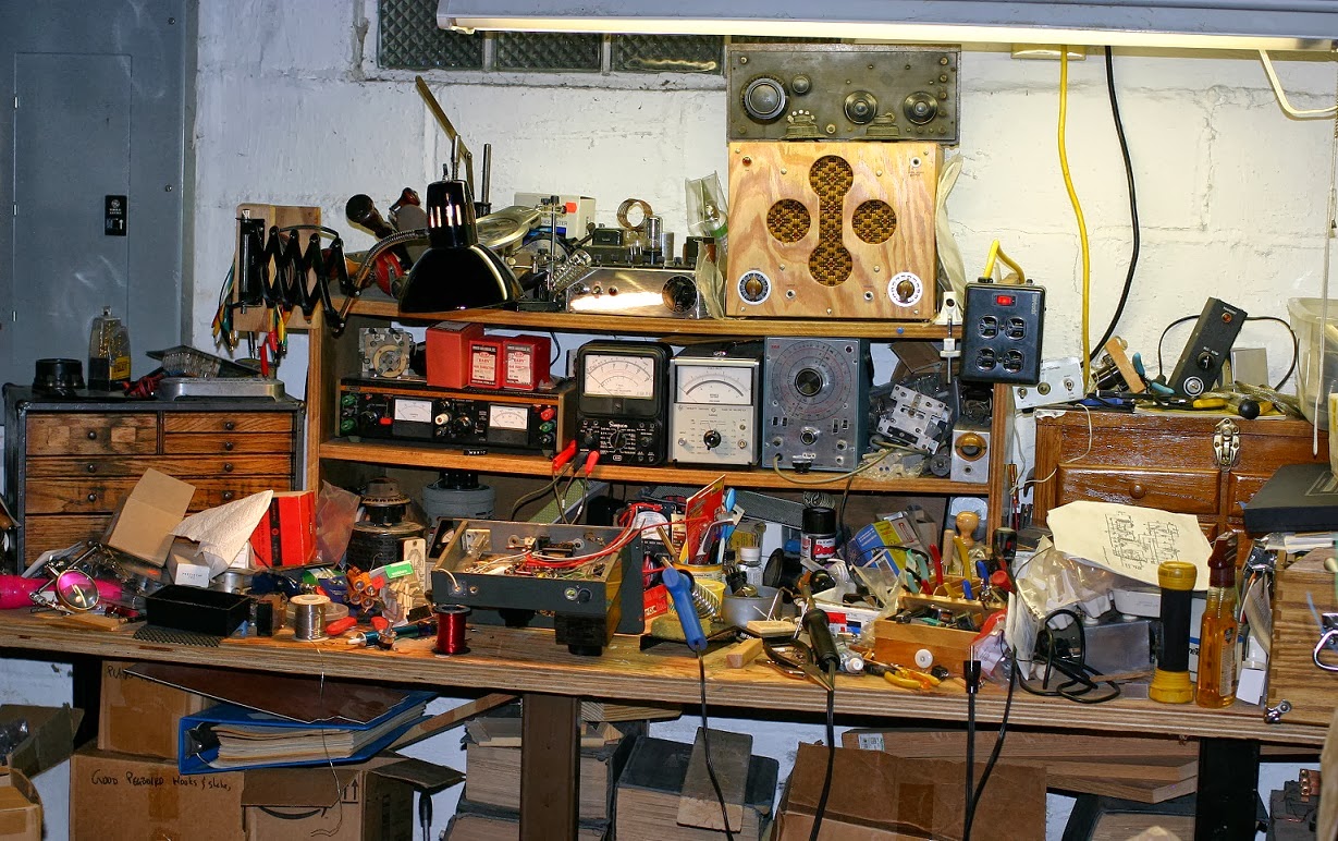
     My workbench is a little chaotic at present.
     As usual, tools have outstripped tool storage and projects have grown to take up the available space.  There's everything from the remains of an old soldering-iron control box and a balanced-line transmit-receive switch that didn't work out (not enough power supply for the relay!) to my QSL-40 transmitter, a box of pegboard hooks and big piece of un-etched PC board.  Somewhere over on the left is a jack box for the CW transmitters (half of them have the key jack on the back, some have heathen connectors that decent folk would never use instead of proper 1/4" two-circuit jacks) and a narrow audio filter.

Tuesday, October 8, 2013

ON THE PROJECT FRONT (TRIPLETT 666-R VOM)

     I finally downloaded the manual for my (obsolete) 666-R VOM -- Triplett's product support is quite good! -- and loaded batteries for the ohmmeter function (2 AAs and a C).  This puts one more meter on my bench for the ongoing Stancor 10P transmitter project, which has been considerably slowed due to lack of time and energy.  The 666-R is the smaller version of their 630; only 1000 Ohms per Volt but a good, solid meter, well worth owning.  It has the same single range control setup as the larger meter:
     The meter leads are, as you might expect, much newer.  I love old meters but old insulation can ruin your day.  (I'm rebuilding a set with super-sharp phonograph-needle tips, something very useful that you absolutely cannot find today.  Mind you, replacement needles for your Victrola are out there, but the once-common test probes with tiny pin-vise chucks for them are no more, probably because of some kind of product liability issue.  Fluke does make some very sharp add-on probe tips, at least.)

    For the Stancor 10P transmitter, I'm bidding on some more plug-in coils of the 50 Watt, end-linked variety that, if I win them, will help a lot with being able to put it on the 80 and 160 Meter bands.  Finding the end-linked ones has been slow; I have coils for 20, 10 and 5 (!) Meters in decent shape, fixed one for 40 Meters that wasn't, and have a couple more in need of much repair.
     I'm still hoping to put them back into useful shape.  It's slow and fiddly work.

Monday, September 16, 2013

A BRILLIANT SET BUILDER, A BRILLIANT KIT DESIGNER

     "Big Nick," KC9KEP, does amazing work.  He's been building classic late-1930s/early-'40s ARRL Handbook receivers (plus some others) and good-looking as the League originals were, his are even better.  If you like building your own ham gear, he's a inspiration.

     On the other side of the Atlantic and a generation or two more recent in technology, the clever Tim Walford (Walford Electronics) has been turning out very nice kits for some time.  I've built one, a nice 80-meter QRP transceiver, and it was fun to build and fun to use on the air.  He's added an antenna tuner and his answer to the problem of providing a variable inductance is one of the best ideas I've seen.  Go to this page and scroll down to Antenna Matching Unit.  Yes, he's using a short piece of ribbon cable and a set of short traces on the PC board to make a coil!  His notes say that particular solid-wire jumper went unavailable, so he's redesigning it for an alternative coil and I'll be interested to learn what that will be. Good equipment from a good guy.

Sunday, September 1, 2013

MILLEN 92201 TRANSMATCH JUNIOR

     What's a transmatch?  It's a device for matching a transmitter (or a receiver) to an antenna, or perhaps the other way around.  It's an impedance-transforming network.  They're pretty common in amateur radio and you can even find high-power versions at some MF AM and SW stations.

     This one was made by the perfectionist James Millen Corporation, their "Junior" model (manual for 92201 here), rated at 150W continuous, 300W peak:

     Internal construction is as clever as most Millen devices.  The split-stator input variable condenser sits on top of a little copper-plated box and the input connector is at the rear-wall end of the box.  What's in the box?  A standing-wave bridge, a pair of directional couplers for providing equal-amplitude coupling-value samples of forward and reflected power.  They go to a front-panel selector switch. Set the front-panel meter to full-scale in "Forward," flip it to "Reverse" and adjust the tuning controls for the lowest reading.  Voila, matched!
     (I removed the cover for these photographs.  It matches the front panel.)

     The output capacitor stands on ceramic pillars: both sides are at an RF potential above ground.

     On the back panel, an extra connector!  It connects to a one-turn loop coupled to the main coil (see the manual), and provides a sample of the signal for an oscilloscope or keying/modulation monitor.

     Found on an auction site for a remarkably low price, this example is unrestored.  Typical of Millen products, it is overbuilt and will only need attention if the meter movement or passive components in the SWR bridge (two diodes, two resistors, a fixed condenser or two) are damaged.

Friday, August 23, 2013

GENERAL RADIO KNOB AND INDEX

     It showed up ay a popular auction site: a genuine GR calibrated knob:
     In the original box (love those fonts!):
      With an "index:"
     Actually, three of them, and that's the part you never see.  Sure, it's just (just?) a line scribed on a piece of metal, the same nickel-plated brass as the calibrated skirt, but it's mounted on a little leaf spring and shaped to ride right on the edge of the calibrations. It beats the usual crude expedients by a long ways.

     There's one fancier replacement, a vernier scale that allows reading the dial to a tenth of a division.  Either one is a nice thing to have when the urge to build some interesting device happens to strike.

Tuesday, July 23, 2013

JOHNSON VIKING CHALLENGER: INDY HAMFEST SWAG, PART FIVE

     E.F. Johnson built a wide range of amateur radio transmitters (among other things), starting in the 1920s.  They hit their stride with the postwar ham radio boom and continued through the early days of SSB.  Every last one of the postwar rigs was a "Viking" something-or-other, which I suppose isn't a huge surprise for a company based in Waseca MN, up there where the descendants of Vikings farmed the land.  The first two, delightful behemoths, were the Viking I and Viking II, but after that, there were Adventurers, Rangers, Navigators, Invaders(!) and the Challenger:
     There was one on a table at the Indy Hamfest, priced over $100 (a bit high, I thought) but the guy was starting to pack up and when he noticed my interest, suggested the price was highly negotiable.  I named a rather low one and he was okay with it -- even added a microphone.

     It's a CW/AM rig, the latter provided by screen-modulating a couple of TV sweep tubes (6DQ6) with a miniature beam tetrode audio tube (6AQ5).  One does not expect high fidelity from this kind of arrangement but given a decent load, it should be adequate.

     The knobs for bandswitch, "excitation" (grid drive) and mode switch are notably missing pointers to tell you where they're set.  The originals were sort of subtle, white plastic pieces glued in at the bottom of the knobs, and I'll have to work out a replacement.

     Does it work?  The seller claimed it did -- it's got Johnson's poorly-documented "push to talk" modification (no schematic, just a step-by-step and partial pictorial) and a connections-unknown mic socket, so I'll want to trace all that out first, clean it up and then, perhaps, power it up via The Gadget. 

     What's The Gadget?  That's a post for another time!

Monday, July 22, 2013

INDY HAMFEST SWAG, PART FOUR

     It's a Weston D.C. Voltmeter, 125 Ohms per Volt:
     Dual-range, which is about par for bench instruments of this age (1920s through '30s) and a handy pair of ranges, too, 0-7 and 0-140 V.  Just right for checking out the 6 V "A" and 135 V (and lower) "B" batteries of a battery radio.

     I paid less than $5.00.

     Sorry about the glare, had to use the flash.

     The March '32 QST used as background is from my collection and features a nice one-tube Hartley oscillator-transmitter using a type '45 tube for the beginning ham.  You thought low-power "QRP" operation was a new thing? Good old George Grammer tells us this transmitter "...will deliver 5 or 6 Watts to the antenna," right in the QRP range.

Sunday, July 21, 2013

INDY HAMFEST SWAG, PART THREE

A "what-is-it?" box.  I was pretty sure I knew...
...Inside, a power transformer, top-hat diode, a lot of R and C and a relay (not visible in this photo) suggested what it might be.  Two pots and a three-circuit jack on the front were a clue.  A pair of insulated screw terminals on the back, marked "S" and "T" were the final giveaway: it's an all-passive-component automatic code keyer!  The two pots are for speed and "weight," the timing ratio between dits (dots) and dahs (dashes).
     For $3.00, it's a good steel minibox and a handful of probably-useful components.

     Elsewhere -- and I should have bought more from the guy, he had a bunch of knobs and dials -- this gadget:
     Just a calibrated knob, you say?  Have a look at the other side!
     It's a nice old vernier dial, made by Crowe up in Chicago.  (You can just read "CRO..." behind the drive at the lower center-left.)  They've been gone for decades but their knobs and dials, etc. still show up.  It's good stuff.  Paid a couple of bucks.  (The one mounting leg that looks broken was made that way.  I don't know why.)  It needs a little fixed scale to be a true "vernier" dial and I may have one the right size.

Sunday, July 14, 2013

INDY HAMFEST SWAG, PART ONE

     I collect glass antenna insulators.  I'd love to use 'em but I worry about breakage.  In the old days, they were attractive targets for vandals....

     Anyway, I picked up four at the Indy hamfest, including a second "screw thread" pattern (center left) and an unusual large-center one with very rounded curves (lower left).  Here's the entire collection:
     There are at least three different hues of glass: clear, yellow and pale blue-green.  The three large insulators at upper right are supposedly from electric fence service!  (Of course, there's a website.)