
Wednesday, December 25, 2013
TYPEWRITER FONTS
Richard Post offers a wonderful collection of free, downloadable typewriter fonts at his site! Royal's "Vogue" font is very similar to the typefaces used for labeling on some Millen ham radio gear.
Sunday, December 8, 2013
CHICAGO RAILROAD FAIR, 1948
Shot on 8mm, right there in 1948 -- and what a collection of vintage transportation hardware!
Friday, November 15, 2013
W9BSP: A HAM'S HAM, A TEACHER'S TEACHER
His name was Marshall H. Ensor. He was a shop teacher in Olathe, Kansas; except for a stint traning radiomen during WW II, he spent most of his life there. He spent it talking to the world and not just idle chatter, either -- Marshall Ensor (and his sister Loretta) spent evenings sending code practice and "teaching radio by radio," a free-for-the-listening lecture course over the powerful W9BSP - W9UA transmitter.
 I'd read all this in back issues of ARRL's magazine QST. What I didn't know is the house where they lived is now a museum and the grounds around it are a park. That big transmitter, in its fine-furniture cabinet, is back on the air again.
As a shop teacher, he reached thousands. There's no way to know how many people, all over the world, he taught about radio. Tens of thousands? (This modest man admitted in a resume sent to the U. S. Navy, "Reputed to have trained more radio operators than any other individual in the United States.") And all from a farmhouse in Kansas.

As a shop teacher, he reached thousands. There's no way to know how many people, all over the world, he taught about radio. Tens of thousands? (This modest man admitted in a resume sent to the U. S. Navy, "Reputed to have trained more radio operators than any other individual in the United States.") And all from a farmhouse in Kansas.
Monday, October 14, 2013
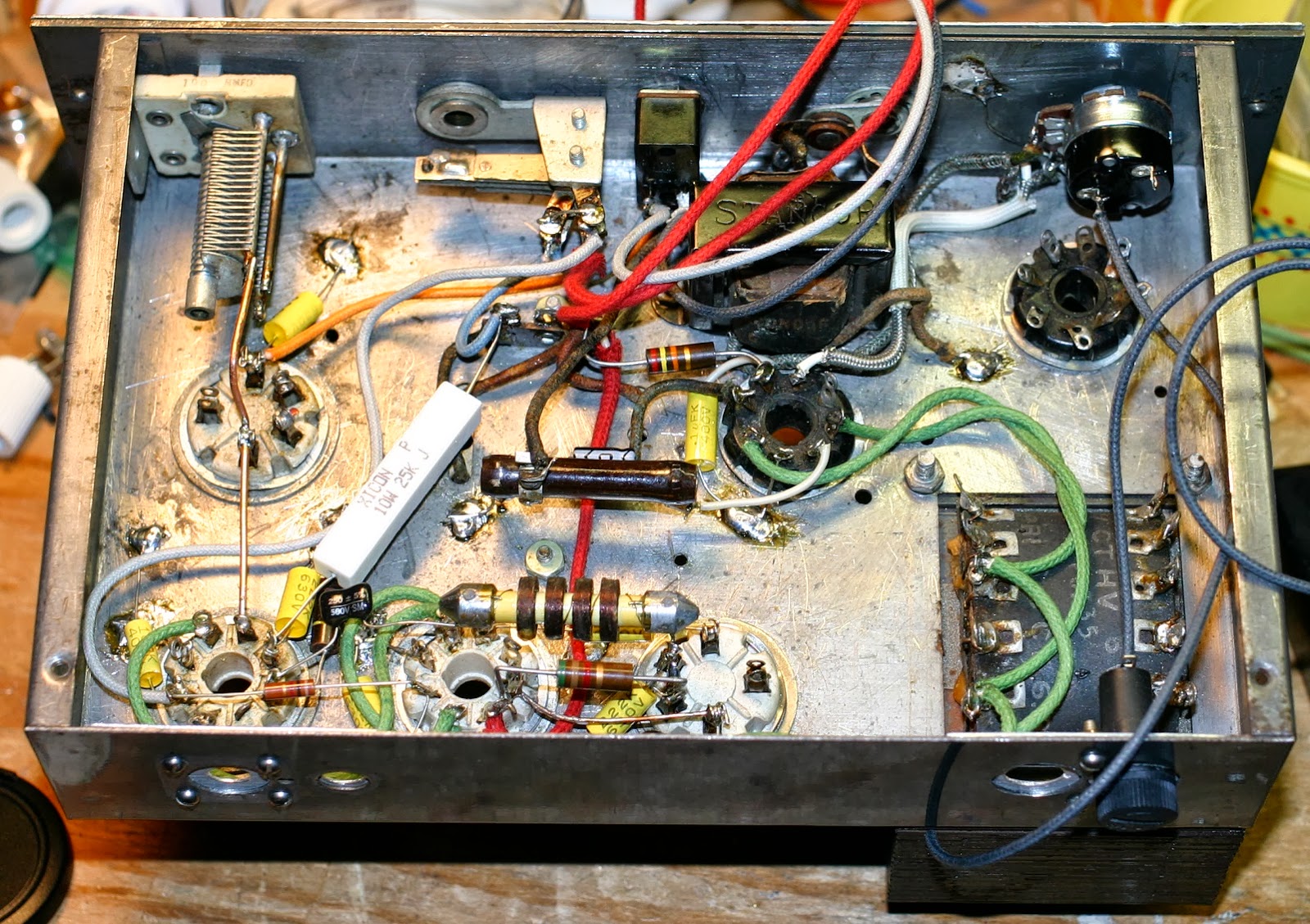
STANCOR 10P TRANSMITTER: UPDATE 11
Mounted and partially wired the volume control, wired up more of the 6L6 RF amp last night:
 Closeup of the tube wiring. Still have the power supply to wire up.
 Inventorying my end-link transmitter coils from Bud and Barker & Williamson, 160, 80, 20, 10 and 5 meters I have in good shape. For 40m, I repaired a coil earlier.
have nothing marked and I'll just have to see if any of the unmarked ones will hit the band. If not, I guess I'll be making one. (My earlier notions were incorrect. For some reason, I thought I'd repaired an 80m coil.)

Thursday, October 10, 2013
STANCOR 10P TRANSMITTER: PART 10
I made some impressive-looking progress this afternoon and stopped to photograph it because it's an example of a technique not everyone knows about: prewiring.
There are a number of controls and jacks mounted on the front panel and it's a pretty tight fit. Rather than mount them and try to get into a small space with needlenose pliers, soldering iron and solder, I wired up the most challenging (a multi-contact jack and a toggle switch) on the bench, and connected the input transformer to the microphone jack before installing it.
This results in quite a few wires cut a little longer than necessary. Yes, there will be some waste and yes, they sell that stuff by the foot, but how much does frustration cost? By color-coding them, it it's easier to sort them out -- blue is plate return, red is B+, gray is cathode and switched ground, and black is ground, which are (mostly) old-time standard colors.
The audio level control remains to be wired up and put in. It mounts right in front of the rectifier tube, so lead dress will be important. You can see the shielded lead from the mic transformer headed over to the empty hole in the front panel; another shielded wire will return from the control to the grid of the modulator tube.
I had a bad moment when I realized I don't own a 1/2" Spintite driver to tighten the nuts of the 1/4" jacks. But I do have a perfectly good modern Klein nutdriver that size.
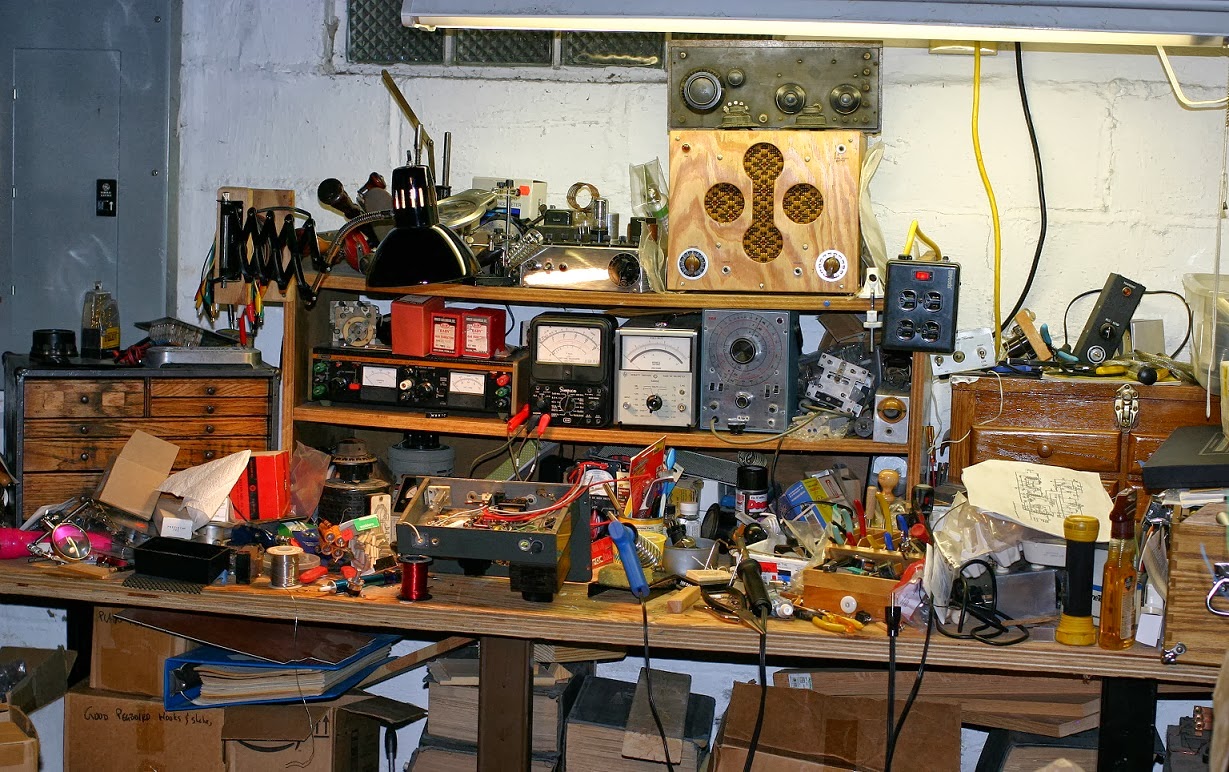
My workbench is a little chaotic at present.
 As usual, tools have outstripped tool storage and projects have grown to take up the available space. There's everything from the remains of an old soldering-iron control box and a balanced-line transmit-receive switch that didn't work out (not enough power supply for the relay!) to my QSL-40 transmitter, a box of pegboard hooks and big piece of un-etched PC board. Somewhere over on the left is a jack box for the CW transmitters (half of them have the key jack on the back, some have heathen connectors that decent folk would never use instead of proper 1/4" two-circuit jacks) and a narrow audio filter.
 |
| Photo is very large if you click on it |
This results in quite a few wires cut a little longer than necessary. Yes, there will be some waste and yes, they sell that stuff by the foot, but how much does frustration cost? By color-coding them, it it's easier to sort them out -- blue is plate return, red is B+, gray is cathode and switched ground, and black is ground, which are (mostly) old-time standard colors.
The audio level control remains to be wired up and put in. It mounts right in front of the rectifier tube, so lead dress will be important. You can see the shielded lead from the mic transformer headed over to the empty hole in the front panel; another shielded wire will return from the control to the grid of the modulator tube.
I had a bad moment when I realized I don't own a 1/2" Spintite driver to tighten the nuts of the 1/4" jacks. But I do have a perfectly good modern Klein nutdriver that size.
My workbench is a little chaotic at present.
Tuesday, October 8, 2013
ON THE PROJECT FRONT (TRIPLETT 666-R VOM)
I finally downloaded the manual for my (obsolete) 666-R VOM -- Triplett's product support is quite good! -- and loaded batteries for the ohmmeter function (2 AAs and a C). This puts one more meter on my bench for the ongoing Stancor 10P transmitter project, which has been considerably slowed due to lack of time and energy. The 666-R is the smaller version of their 630; only 1000 Ohms per Volt but a good, solid meter, well worth owning. It has the same single range control setup as the larger meter:
 The meter leads are, as you might expect, much newer. I love old meters but old insulation can ruin your day. (I'm rebuilding a set with super-sharp phonograph-needle tips, something very useful that you absolutely cannot find today. Mind you, replacement needles for your Victrola are out there, but the once-common test probes with tiny pin-vise chucks for them are no more, probably because of some kind of product liability issue. Fluke does make some very sharp add-on probe tips, at least.)
For the Stancor 10P transmitter, I'm bidding on some more plug-in coils of the 50 Watt, end-linked variety that, if I win them, will help a lot with being able to put it on the 80 and 160 Meter bands. Finding the end-linked ones has been slow; I have coils for 20, 10 and 5 (!) Meters in decent shape, fixed one for 40 Meters that wasn't, and have a couple more in need of much repair.
 I'm still hoping to put them back into useful shape. It's slow and fiddly work.

For the Stancor 10P transmitter, I'm bidding on some more plug-in coils of the 50 Watt, end-linked variety that, if I win them, will help a lot with being able to put it on the 80 and 160 Meter bands. Finding the end-linked ones has been slow; I have coils for 20, 10 and 5 (!) Meters in decent shape, fixed one for 40 Meters that wasn't, and have a couple more in need of much repair.

Monday, September 16, 2013
A BRILLIANT SET BUILDER, A BRILLIANT KIT DESIGNER
"Big Nick," KC9KEP, does amazing work. He's been building classic late-1930s/early-'40s ARRL Handbook receivers (plus some others) and good-looking as the League originals were, his are even better. If you like building your own ham gear, he's a inspiration.
On the other side of the Atlantic and a generation or two more recent in technology, the clever Tim Walford (Walford Electronics) has been turning out very nice kits for some time. I've built one, a nice 80-meter QRP transceiver, and it was fun to build and fun to use on the air. He's added an antenna tuner and his answer to the problem of providing a variable inductance is one of the best ideas I've seen. Go to this page and scroll down to Antenna Matching Unit. Yes, he's using a short piece of ribbon cable and a set of short traces on the PC board to make a coil! His notes say that particular solid-wire jumper went unavailable, so he's redesigning it for an alternative coil and I'll be interested to learn what that will be. Good equipment from a good guy.
On the other side of the Atlantic and a generation or two more recent in technology, the clever Tim Walford (Walford Electronics) has been turning out very nice kits for some time. I've built one, a nice 80-meter QRP transceiver, and it was fun to build and fun to use on the air. He's added an antenna tuner and his answer to the problem of providing a variable inductance is one of the best ideas I've seen. Go to this page and scroll down to Antenna Matching Unit. Yes, he's using a short piece of ribbon cable and a set of short traces on the PC board to make a coil! His notes say that particular solid-wire jumper went unavailable, so he's redesigning it for an alternative coil and I'll be interested to learn what that will be. Good equipment from a good guy.
Friday, September 6, 2013
MODERN 36" PENNYFARTHINGS: COKER AND QU-AX
At the WARMfest last weekend, I met a fellow riding a Coker Wheelman pennyfarthing, with the same wheel size as my QU-AX.
Both have similar rake angles, pneumatic tires and the main wheel is a yard across -- but that's about it for similarities:
They're both nice-looking ordinaries and attract a lot of interest. While the Coker does have a brake on the main wheel, the rider I met admitted he doesn't use it much. Meeting him made me wish I'd've ridden mine to the event; there aren't so many of us on pennyfarthings, still less the modern versions.
Both have similar rake angles, pneumatic tires and the main wheel is a yard across -- but that's about it for similarities:
 |
| Coker at left, QU-AX at right |
Sunday, September 1, 2013
MILLEN 92201 TRANSMATCH JUNIOR
What's a transmatch? It's a device for matching a transmitter (or a receiver) to an antenna, or perhaps the other way around. It's an impedance-transforming network. They're pretty common in amateur radio and you can even find high-power versions at some MF AM and SW stations.
This one was made by the perfectionist James Millen Corporation, their "Junior" model (manual for 92201 here), rated at 150W continuous, 300W peak:

Internal construction is as clever as most Millen devices. The split-stator input variable condenser sits on top of a little copper-plated box and the input connector is at the rear-wall end of the box. What's in the box? A standing-wave bridge, a pair of directional couplers for providing equal-amplitude coupling-value samples of forward and reflected power. They go to a front-panel selector switch. Set the front-panel meter to full-scale in "Forward," flip it to "Reverse" and adjust the tuning controls for the lowest reading. Voila, matched!
 (I removed the cover for these photographs. It matches the front panel.)
The output capacitor stands on ceramic pillars: both sides are at an RF potential above ground.

On the back panel, an extra connector! It connects to a one-turn loop coupled to the main coil (see the manual), and provides a sample of the signal for an oscilloscope or keying/modulation monitor.

Found on an auction site for a remarkably low price, this example is unrestored. Typical of Millen products, it is overbuilt and will only need attention if the meter movement or passive components in the SWR bridge (two diodes, two resistors, a fixed condenser or two) are damaged.
This one was made by the perfectionist James Millen Corporation, their "Junior" model (manual for 92201 here), rated at 150W continuous, 300W peak:

Internal construction is as clever as most Millen devices. The split-stator input variable condenser sits on top of a little copper-plated box and the input connector is at the rear-wall end of the box. What's in the box? A standing-wave bridge, a pair of directional couplers for providing equal-

The output capacitor stands on ceramic pillars: both sides are at an RF potential above ground.

On the back panel, an extra connector! It connects to a one-turn loop coupled to the main coil (see the manual), and provides a sample of the signal for an oscilloscope or keying/modulation monitor.

Found on an auction site for a remarkably low price, this example is unrestored. Typical of Millen products, it is overbuilt and will only need attention if the meter movement or passive components in the SWR bridge (two diodes, two resistors, a fixed condenser or two) are damaged.
Friday, August 23, 2013
GENERAL RADIO KNOB AND INDEX
It showed up ay a popular auction site: a genuine GR calibrated knob:
 In the original box (love those fonts!):
 With an "index:"
 Actually, three of them, and that's the part you never see. Sure, it's just (just?) a line scribed on a piece of metal, the same nickel-plated brass as the calibrated skirt, but it's mounted on a little leaf spring and shaped to ride right on the edge of the calibrations. It beats the usual crude expedients by a long ways.
There's one fancier replacement, a vernier scale that allows reading the dial to a tenth of a division. Either one is a nice thing to have when the urge to build some interesting device happens to strike.


There's one fancier replacement, a vernier scale that allows reading the dial to a tenth of a division. Either one is a nice thing to have when the urge to build some interesting device happens to strike.
Saturday, August 3, 2013
INDIANA STATE FAIR RETROTECH
The Pioneer Village area of the Indiana State Fair is a hotbed of retrotech and, as it turned out, a few vendors thereof as well. I passed up a well-worn set of radio headphones, 1920s or '30s vintage, but these small items caught my attention and had to come home:
 The pens, by the Bridgeport Pen Co. of the Connecticut town of the same name, are an unusual design, sized for sign or poster work and intended to be used with India-type drawing ink. The narrowest one is turned so you can see the corrugated brass ink retainer. They show up fairly often.
The pencil saver is a clever gadget dating back to Victorian times, allowing you to use a pencil right down to the stub -- and in the stored position, it keeps the point out of harm's way. This one is a bit newer, 1930s perhaps, with a well-petrified eraser. There's a little drawing of a cave entrance on the label, with the legend, "Souvenir of Mark Twain Cave, Hannibal, Mo." The entrance still looked the same in a 1956 photograph and may not be much changed even today.
The trammel (or "beam compass"), made by Feranco Products (Ferance Construction Co. of Penfield, N.Y.) is a very small example; large trammel points that clamp on a framing square or yardstick are more commonly seen. Neither ZIP nor Zone code on the address and the points proper look to be zamak -- 1930s though 1950s? This one easily scribes circles up to 12 inches in diameter. The previous owner left the lead properly sharpened, too. There's a set of actual scribe points (the other end has a stepped drafting type), extra lead and spare clamp screws along with their G U A R A N T E E. It may have originally contained more beams, which the clamp screws would have held together for making larger circles.
Prices? Including tax, I paid more for lunch (a ribeye sandwich and a glass of pop) than I did for any of it -- $10 total for the three pens, the same for the beam compass, $4 for the pencil saver. This compares rather favorably with asking prices online and these are useful items.
Wednesday, July 31, 2013
ELECTRO-VOICE V-1 RIBBON MICROPHONE
Is there any mellower microphone than a good ribbon? These velocity mics are strikingly different to most other transducers -- for one thing, the ribbon is operating above its resonant frequency, rather than below it. No other microphone works that way and it's part of their warmth and lack of "proximity effect." "off mic" sound even at fairly large distances, as long as the speaker is on-axis, facing one of the wider sides. (I was wrong earlier, ribbon mics actually have a lot of up-close bass-boosting proximity effect. I never worked one very closely, they're very sensitive to plosive sounds.)
A long time ago, I owned an RCA 44BX, the iconic broadcast microphone. I fell on hard times and sold it (hoping to buy it back some day) and the mic subsequently had a hard life (damaged ribbon, some sort of plating job, paperweight) until I lost track of it. So when a "baby brother" (about half-size) made by Indiana's own Electro-Voice* turned up for just over $100 at an antique mall, I bought it on sight.
Of course it was dead. Responded slightly to a fingernail tapped on the frame but not at all to sound, which is a sure sign the ribbon is against a pole piece, or jammed up with lint. Close examination showed the ribbon well out of alignment and crumpled. I wrapped it up and set to one side, thinking some day I'd nerve up to try rebuilding it--
Fast-forward a couple of years; browsing for a microphone for work, I stumbled across AEA, who still make classic RCA microphones. They're quite expensive and worth every cent.
They're also beautiful.
If you look carefully at their home page, you'll see a "repair form" link. And not just the RCA types; they sell and support the STC/Coles mics made in the UK, too. So I called and asked their ace service guy (fixing ribbon mics is the darkest of Dark Arts, combining watchmaking, ship-in-a-bottle skills and fine-arts-grade audio talent, and that's just for a start) if he'd consider fixing an Electro-Voice V-1?
"There's a V-2 on my bench right now, so that'd be a yes."
I filled out the form and dithered for several weeks. This could be costly! On the other hand, while there are several firms making ribbon mics these days (with varying degrees of success. AEA is the gold standard they aspire towards), repairing them is a much scarcer skill and very nearly died out once already. Shipped the mic and crossed my fingers.
Several weeks later, at the Dayton Hamvention of all places, my celphone rang. AEA: "Hey, what's that weird connector on your V-1? We haven't got anything that will mate with it!"
I had to laugh. "Sorry, I forgot it's only 1937 in my basement. It's an early hi-Z connector, used on mics and test gear through the 1960s. You've called me at the one place where I can be sure of finding one; I'll make up an adapter and send it to you."
The V-1 uses a "spot" connector. All later E-V ribbon mics were selectable-impedance and had either an unterminated cable or one of the early multi-pin connectors.
About a month later, they called with my bill. New ribbon, new magnets, new rubber shockmount, alignment and test, bench time-- I braced for the bottom line.
About $150. Well under what I was anticipating.
Mind you, by their standards, the little E-V is a fairly undemanding repair and the cast-zinc base prevents much cosmetic refinishing (zamak is unpredictable stuff and only gets more so the more you mess with it). The end result looks better than it did when I bought it, with the grill all clean and shiny, and sounds great. Output's not very high -- that's a small ribbon, after all -- but well within what a decent mic preamp can deal with.
I'm tempted to ask them if they'll look at my Amperite ribbon mic:
 These were, shall we say, built to a price. This one hasn't suffered a lot of zinc-alloy creep, but it's seen entirely too much knocking around and the guy I bought it from, despite his assurances to take exceeding great care, packed it for shipment like you'd pack a brickbat: no padding at all. ...I think maybe I'll wait a bit before sending this in. And maybe bake some cookies to send along with it by way of apology, too.
Electro-Voice V-1: good mic, back in service.
AEA: They've made me even more of a fan than I already was!
_____________________________________________
* E-V started out in South Bend, eventually jumping the border for Buchanan, Michigan. They've built good mics since Day One, if you ask me.
A long time ago, I owned an RCA 44BX, the iconic broadcast microphone. I fell on hard times and sold it (hoping to buy it back some day) and the mic subsequently had a hard life (damaged ribbon, some sort of plating job, paperweight) until I lost track of it. So when a "baby brother" (about half-size) made by Indiana's own Electro-Voice* turned up for just over $100 at an antique mall, I bought it on sight.
 |
| "After." The base is not original. |
Fast-forward a couple of years; browsing for a microphone for work, I stumbled across AEA, who still make classic RCA microphones. They're quite expensive and worth every cent.
They're also beautiful.
If you look carefully at their home page, you'll see a "repair form" link. And not just the RCA types; they sell and support the STC/Coles mics made in the UK, too. So I called and asked their ace service guy (fixing ribbon mics is the darkest of Dark Arts, combining watchmaking, ship-in-a-bottle skills and fine-arts-grade audio talent, and that's just for a start) if he'd consider fixing an Electro-Voice V-1?
"There's a V-2 on my bench right now, so that'd be a yes."
I filled out the form and dithered for several weeks. This could be costly! On the other hand, while there are several firms making ribbon mics these days (with varying degrees of success. AEA is the gold standard they aspire towards), repairing them is a much scarcer skill and very nearly died out once already. Shipped the mic and crossed my fingers.
Several weeks later, at the Dayton Hamvention of all places, my celphone rang. AEA: "Hey, what's that weird connector on your V-1? We haven't got anything that will mate with it!"
I had to laugh. "Sorry, I forgot it's only 1937 in my basement. It's an early hi-Z connector, used on mics and test gear through the 1960s. You've called me at the one place where I can be sure of finding one; I'll make up an adapter and send it to you."
The V-1 uses a "spot" connector. All later E-V ribbon mics were selectable-impedance and had either an unterminated cable or one of the early multi-pin connectors.
About a month later, they called with my bill. New ribbon, new magnets, new rubber shockmount, alignment and test, bench time-- I braced for the bottom line.
About $150. Well under what I was anticipating.
Mind you, by their standards, the little E-V is a fairly undemanding repair and the cast-zinc base prevents much cosmetic refinishing (zamak is unpredictable stuff and only gets more so the more you mess with it). The end result looks better than it did when I bought it, with the grill all clean and shiny, and sounds great. Output's not very high -- that's a small ribbon, after all -- but well within what a decent mic preamp can deal with.
I'm tempted to ask them if they'll look at my Amperite ribbon mic:

Electro-Voice V-1: good mic, back in service.
AEA: They've made me even more of a fan than I already was!
_____________________________________________
* E-V started out in South Bend, eventually jumping the border for Buchanan, Michigan. They've built good mics since Day One, if you ask me.
Tuesday, July 23, 2013
JOHNSON VIKING CHALLENGER: INDY HAMFEST SWAG, PART FIVE
E.F. Johnson built a wide range of amateur radio transmitters (among other things), starting in the 1920s. They hit their stride with the postwar ham radio boom and continued through the early days of SSB. Every last one of the postwar rigs was a "Viking" something-or-other, which I suppose isn't a huge surprise for a company based in Waseca MN, up there where the descendants of Vikings farmed the land. The first two, delightful behemoths, were the Viking I and Viking II, but after that, there were Adventurers, Rangers, Navigators, Invaders(!) and the Challenger:
 There was one on a table at the Indy Hamfest, priced over $100 (a bit high, I thought) but the guy was starting to pack up and when he noticed my interest, suggested the price was highly negotiable. I named a rather low one and he was okay with it -- even added a microphone.
It's a CW/AM rig, the latter provided by screen-modulating a couple of TV sweep tubes (6DQ6) with a miniature beam tetrode audio tube (6AQ5). One does not expect high fidelity from this kind of arrangement but given a decent load, it should be adequate.
The knobs for bandswitch, "excitation" (grid drive) and mode switch are notably missing pointers to tell you where they're set. The originals were sort of subtle, white plastic pieces glued in at the bottom of the knobs, and I'll have to work out a replacement.
Does it work? The seller claimed it did -- it's got Johnson's poorly-documented "push to talk" modification (no schematic, just a step-by-step and partial pictorial) and a connections-unknown mic socket, so I'll want to trace all that out first, clean it up and then, perhaps, power it up via The Gadget.
What's The Gadget? That's a post for another time!
Monday, July 22, 2013
INDY HAMFEST SWAG, PART FOUR
It's a Weston D.C. Voltmeter, 125 Ohms per Volt:
 Dual-range, which is about par for bench instruments of this age (1920s through '30s) and a handy pair of ranges, too, 0-7 and 0-140 V. Just right for checking out the 6 V "A" and 135 V (and lower) "B" batteries of a battery radio.
I paid less than $5.00.
Sorry about the glare, had to use the flash.
The March '32 QST used as background is from my collection and features a nice one-tube Hartley oscillator-transmitter using a type '45 tube for the beginning ham. You thought low-power "QRP" operation was a new thing? Good old George Grammer tells us this transmitter "...will deliver 5 or 6 Watts to the antenna," right in the QRP range.
Sunday, July 21, 2013
INDY HAMFEST SWAG, PART THREE
A "what-is-it?" box. I was pretty sure I knew...
 ...Inside, a power transformer, top-hat diode, a lot of R and C and a relay (not visible in this photo) suggested what it might be. Two pots and a three-circuit jack on the front were a clue. A pair of insulated screw terminals on the back, marked "S" and "T" were the final giveaway: it's an all-passive-component automatic code keyer! The two pots are for speed and "weight," the timing ratio between dits (dots) and dahs (dashes).
For $3.00, it's a good steel minibox and a handful of probably-useful components.
Elsewhere -- and I should have bought more from the guy, he had a bunch of knobs and dials -- this gadget:
 Just a calibrated knob, you say? Have a look at the other side!
 It's a nice old vernier dial, made by Crowe up in Chicago. (You can just read "CRO..." behind the drive at the lower center-left.) They've been gone for decades but their knobs and dials, etc. still show up. It's good stuff. Paid a couple of bucks. (The one mounting leg that looks broken was made that way. I don't know why.) It needs a little fixed scale to be a true "vernier" dial and I may have one the right size.

For $3.00, it's a good steel minibox and a handful of probably-useful components.
Elsewhere -- and I should have bought more from the guy, he had a bunch of knobs and dials -- this gadget:


Monday, July 15, 2013
INDY HAMFEST SWAG, PART TWO
A low-impedance/high-impedance microphone matching transformer:
 This example arrived with some barbaric ham-radio mic connector on the low-impedance side, a three-pin, threaded-shell item. ETA: I found the mating connector in my collection! This is why you save 'em.
The transformer is a Shure Brothers A86A.
 "Model A86A is a high-quality cable-type transformer which offers additional versatility when used in conjunction with Shure Models 55,556, and 51 Dynamic Microphones, which employ the impedance matching switch. It solves the frequent problem of installations requiring long lengths of microphone cables without the loss of high-frequency response. Model A86A matches 35 to 50 and 150 to 250 ohm microphones to high impedance amplifier input. Compact, sturdy.
Case diameter 1-5/8", length 2-7/8", 7 foot cable. Shipping weight 1-1/2 pounds.
Model A86A. Code: RUDEB. List Price $13.10"
(Link to a Shure catalog listing it at Preservation Sound.)
That was pretty a high price, back when this was new. Frequency response is cited as "within 1 dB, 20 to 20,000 cps," which is darned good. The various low impedances are selected by removing three screws on the low-Z side, opening the case up and moving a jumper.
Does this one work? I don't know yet. It was priced to move at $3.00 and for that kind of money, worth finding out.

The transformer is a Shure Brothers A86A.

Case diameter 1-5/8", length 2-7/8", 7 foot cable. Shipping weight 1-1/2 pounds.
Model A86A. Code: RUDEB. List Price $13.10"
(Link to a Shure catalog listing it at Preservation Sound.)
That was pretty a high price, back when this was new. Frequency response is cited as "within 1 dB, 20 to 20,000 cps," which is darned good. The various low impedances are selected by removing three screws on the low-Z side, opening the case up and moving a jumper.
Does this one work? I don't know yet. It was priced to move at $3.00 and for that kind of money, worth finding out.
Sunday, July 14, 2013
INDY HAMFEST SWAG, PART ONE
I collect glass antenna insulators. I'd love to use 'em but I worry about breakage. In the old days, they were attractive targets for vandals....
Anyway, I picked up four at the Indy hamfest, including a second "screw thread" pattern (center left) and an unusual large-center one with very rounded curves (lower left). Here's the entire collection:
 There are at least three different hues of glass: clear, yellow and pale blue-green. The three large insulators at upper right are supposedly from electric fence service! (Of course, there's a website.)
Anyway, I picked up four at the Indy hamfest, including a second "screw thread" pattern (center left) and an unusual large-center one with very rounded curves (lower left). Here's the entire collection:

A SIMPLE AUDIO SPLITTING/COMBINING PAD
This is a neat trick for professional balanced audio applications, where a stereo signal needs to be "summed" to mono or a mono one split to two destinations.
 It depends on all the sources and loads being the same impedance, which the resistors match, 600 Ohms in this (typical) example. Isolation between the two inputs (or outputs) is very good and insertion loss is low.
Modern practice tends more to quite low-Z sources[1] and very high-impedance loads. With that, "splitting" one source to several destinations can be a simple (if sloppy) process of paralleling but look out if any one of them gets shorted! This "Bridge" (as in Wheatstone) pad can be adapted to the low-Z source/High-Z load system by "building out" the pad inputs with pairs of series resistors and adding a fourth 604 Ohm[2] resistor on the load side, but insertion loss will go up as will complexity; a "branching" pad is probably easier--
 --But the isolation between ports is worse. Still (and especially with a modern very-low-impedance source), a short on any one branch won't silence the others. (Expanding this to more ports results in increased loss and different resistor values but simple algebra will tell you what they are.)
This is a little off-topic but analog audio, especially balanced audio, has become more and more "black magic" as the digital age advances. Perhaps it will be of use to some of the ham operators running AM, who sometimes use older audio mixers and feed multiple transmitters, some of which are former AM broadcast rigs.
Most sound starts out analog and ends up that way, too.
_________________________________
1. Some "zero-Ohm" sources are more zero than others. Back when Purdue University's WBAA still used Ralph W. Townsely's amazing homebrew (tube-type!) audio console, the line outputs were very high-fidelity audio power amps set for extremely low output impedance and technically-savvy visitors might be handed a paperclip by the (irreverent) student operators and invited to "short out the Line audio." All that happened was the paperclip got hot; the audio level never changed. Please don't try that with the "0 Ohm" analog outputs of most pro audio gear -- your results will be quite different.
2. Why 604 Ohms? It's the nearest 1% metal-film resistor value to 600. 1% resistors cost pennies these days but you could use the closest from the (even cheaper) 5/10/20% carbon resistor bins, either 560 or 620 Ohms. If you're feeding something critical like a passive equalizer, you may be able to tell the difference.

Modern practice tends more to quite low-Z sources[1] and very high-impedance loads. With that, "splitting" one source to several destinations can be a simple (if sloppy) process of paralleling but look out if any one of them gets shorted! This "Bridge" (as in Wheatstone) pad can be adapted to the low-Z source/High-Z load system by "building out" the pad inputs with pairs of series resistors and adding a fourth 604 Ohm[2] resistor on the load side, but insertion loss will go up as will complexity; a "branching" pad is probably easier--

This is a little off-topic but analog audio, especially balanced audio, has become more and more "black magic" as the digital age advances. Perhaps it will be of use to some of the ham operators running AM, who sometimes use older audio mixers and feed multiple transmitters, some of which are former AM broadcast rigs.
Most sound starts out analog and ends up that way, too.
_________________________________
1. Some "zero-Ohm" sources are more zero than others. Back when Purdue University's WBAA still used Ralph W. Townsely's amazing homebrew (tube-type!) audio console, the line outputs were very high-fidelity audio power amps set for extremely low output impedance and technically-savvy visitors might be handed a paperclip by the (irreverent) student operators and invited to "short out the Line audio." All that happened was the paperclip got hot; the audio level never changed. Please don't try that with the "0 Ohm" analog outputs of most pro audio gear -- your results will be quite different.
2. Why 604 Ohms? It's the nearest 1% metal-film resistor value to 600. 1% resistors cost pennies these days but you could use the closest from the (even cheaper) 5/10/20% carbon resistor bins, either 560 or 620 Ohms. If you're feeding something critical like a passive equalizer, you may be able to tell the difference.
Thursday, June 13, 2013
TUBE-TYPE MIC MIXER, PART 2
A reader complimented the schematic I posted yesterday. Of course, that's the "clean copy." Here's the one I drew as I traced it:
 You will note several layout errors that are corrected in the later version -- don't know why I omitted the headphone jack wiring in that one, though. Schematic drawings can nearly always be improved after the first draft gets everything on paper (or on the screen, if you work that way). The rules are simple, applying them sometimes isn't.
And here's what I traced:
 The Thordarson "Tru-Fidelity" mic transformers are not original -- the fellow who gave me the mixer salvaged the original UTC transformers. The Thordarsons are at least as good. They're also larger. I'm not happy with the length of unshielded wire in the grid leads, it will want changed. Looks like I took most of the wire harness lacing out when I traced it, too, so that needs redone as well. I wonder how those Sprague "Atoms" electrolytics are holding up? (They're on the terminal board behind the right-hand mic jack.)
Back panel:
 Blank and ready for call letters! (It's traditional.)
2" Cannon connectors, with a penny for scale and ancient masking tape stuck on the chassis:

12-pin Jones plug, holes where a previous user had relocated the output terminals, fuseholder:

Rannie the cat loves my fancy screwdriver set:
 This made disassembly a little more difficult.
(Here's another take on a small mic mixer, kind of interesting...if you have the parts.)

And here's what I traced:

Back panel:

2" Cannon connectors, with a penny for scale and ancient masking tape stuck on the chassis:

12-pin Jones plug, holes where a previous user had relocated the output terminals, fuseholder:

Rannie the cat loves my fancy screwdriver set:

(Here's another take on a small mic mixer, kind of interesting...if you have the parts.)
Wednesday, June 12, 2013
TUBE-TYPE MIC MIXER
It's been awhile since I traced the circuit and got it working:

Naturally, it was not working when I took it down from the shelf. Time to get out the signal tracer.
 At some point before I got it, the front panel was covered in wood-grain laminate. I'm thinking a nice coat of plastic-friendly matte black would do it a world of good. And perhaps some RCA-type knobs that had not been painted, too.
(A word about the '2" Cannon' notation for the input connectors: that's what they are, great big old-fashioned microphone sockets. A mic-connector roundup post is in the works to provide examples.)

Naturally, it was not working when I took it down from the shelf. Time to get out the signal tracer.

(A word about the '2" Cannon' notation for the input connectors: that's what they are, great big old-fashioned microphone sockets. A mic-connector roundup post is in the works to provide examples.)
Thursday, June 6, 2013
THE FIRST PLAY-BY-PLAY MAN
In fact, he probably invented the idea. And he was a Hoosier.
...It was The Big Game -- and not a home game for his school's team. The year was 1903. University of Michigan student, Indiana resident (and part-time telegrapher) Floyd J. "Jack" Mattice had already dreamed up (and sold to Western Union!) the notion of having sports-knowledgeable telegraphers transmit moment-by-moment scores and high points directly, instead of waiting on copy from print reporters and now he'd come up with another idea: a long-distance telephone line. He'd describe the game to the other students back at UM as it happened.
Bell Telephone installed a phone booth on 40-foot poles along the sidelines at mid-field and a direct line back to the auditorium at UM. Shortly before the game began, Mattice climbed up and placed the call--
But remember, this is 1903. Electrical amplification is still several years away. Backstage, ten more sports-fan students were listening in, each one in turn memorizing a few minutes' play and rushing onstage to relay it to the audience, and then back to his listening post as the next "sportscaster" took over, on after another.
It was a popular notion. At UM, the practice continued until radio broadcasting took over in the 1920s. As for Mattice, he had another career; you see, he'd arrived at college already a member of the bar. After graduation, he went home to Rochester and practiced law, serving a couple terms as county prosecutor. Even that wasn't enough -- during WW I, he went to work for the Bureau of Investigation's office in Indianapolis and then at the U. S. District Attorney's office. He went back into private practice a few years later and then served in various posts with the city, then back to Federal work during WW II, ending up as a prosecutor at the war crimes trials in Japan.
Still, inventing sportscasting probably made more people happy than any of his legal work. He retired to Rochester and passed away in 1971. He maintained a lifelong interest in telegraphy and if you've ever wondered about the curious number of attorney/sportscasters (Howard Cosell, for instance), while I don't think Mr. Mattice can be blamed for it, he was certainly one of the first examples.
(Crossposted from my personal/political blog.)
Thursday, May 23, 2013
IT'S A KLUGE
Once, there was a real Kluge:
 Myron E. Kluge, in fact. In the years after WW II, he promised big things in the ham radio field, produced some fascinating ads featuring the very first "desk kilowatt" (a metal desk with a 1000W amplifier in it, a concept E. F. Johnson later built and sold in fair numbers) and faded from sight.
Kluge Electronics had some interest in television (the 1946 "Radio" Handbook has an ad featuring the TV racks at Kluge Labs, looking neither more nor less of a kluge than anyone else's) and early FM but it either found a very obscure niche to vanish into or failed entirely.
Update: Some kind of a (commercial broadcast?) Kludge transmitter, seen in 2007 by Garett Wollman in Salt Lake City, possibly at the KSL transmitter site. Pity it's not in better shape. Clearly, there's a story to be told about Kluge, though it may be impossible to ferret it out.
Sunday, May 19, 2013
DAYTON HAMVENTION 2013
"Turk" Turon and I were at the Dayton Hamvention the better part of Friday and we saw about half. It was amazing. I passed up an early Globe transmitter -- next step smaller than the Globe King. Shoulda, woulda-- Could not lift it. Priced to move at $300 and in working condition. Oh, if only!
(I did manage a smaller/newer rig, a Heathkit DX-60, also said to be working. We'll see.)
Some rigs were way too big to move:
 Love that paint-job! (Here's a closer look.)
This is the RF side; audio is the same size, with two more final-stage tubes and a nice window to enjoy them through. Be sure to tune for minimum meltage.
 It's a Gates 1kW job, and very large for its size; but that just makes it easier to work on. There was a Collins 20V in front of it, of which I hope to post pictures later. Notice the bead-chain drive crossing the window? The output tuning network is on the right side of the cabinet -- but Gates did't want all the knobs over there, that wouldn't be balanced! So they extended it. That means you'll be retuning a bit after start-up until cabinet temperature stabilizes: all that extra mechanical folderol carries a price. The 20V has much the same trick, only with brass bead-chain, aluminum drive wheels and a steel cabinet, all mounted high up in a physically-smaller transmitter at the same power level, or, "Please touch up Loading adjustment once an hour until noon," as the note at one station read; they only ran the 20V one day a week and it woke slowly.
Some hair was movingly big.
 Kristen had admirers wherever she went.
Table of Vibroplexes.
 The new owner is just out of the shot. Have I mentioned how good Vibroplex parts support is these days? It is and you can thank him for it.
Turk found a man-sized soldering copper.
 Well, more like statue-sized. When they build the Radio Row monument in NYC, it'll be holding one of those, looking out at Lady Liberty as if wondering about asking to borrow the torch.
(I did manage a smaller/newer rig, a Heathkit DX-60, also said to be working. We'll see.)
Some rigs were way too big to move:

This is the RF side; audio is the same size, with two more final-stage tubes and a nice window to enjoy them through. Be sure to tune for minimum meltage.

Some hair was movingly big.

Table of Vibroplexes.

Turk found a man-sized soldering copper.

Sunday, May 12, 2013
STANCOR 10P PROGRESS REPORT 9
Wiring. A lot of thinking, rethinking and ground points needing to be added. Also, I really need to stock up on cloth-covered wire, the good stuff.
 Crystal oscillator, wired. RF power amplifier, mostly wired -- tank circuit being the main thing to complete. Modulator, partially wired. Power supply, still to do.
It's just about to the "install front panel and controls" point.

It's just about to the "install front panel and controls" point.
Tuesday, May 7, 2013
HISTORICAL RESEARCH: NEWSPAPER ARCHIVES
Looking for more information about the earliest days of television and FM in Indianapolis, it occurred to me that newspaper archives would be a great source; after all, the city has had some great newspapers: the Indianapolis Times (d., 1965), the Indianapolis News (b., 1869 - d., 1999, after a long illness; survived for a short while by Herman Hoglebogle) and the Indianapolis Star; two of those papers even owned radio stations, so there must be plenty of news about local radio to be found.
Possibly there is, but not online from those sources; the "morgue" files of the Times and the News appear nowhere and the Star has a gap from 31 December 1922 to 21 May 1991.
One newspaper has extensive archives, wonderfully searchable, compiled by IUPUI: the Indianapolis Recorder, which has served the city's African-American community since its inception in 1895. And on 13 July 1946, WABW shows up, in an ad for a song to be broadcast on the 17th of that month at 5:30 p.m.. This was a standalone FM, in a time when few FM radios were available, so it's especially interesting to note the ad doesn't list the frequency.
After the ownership and call letter change, WXLW and (simulcast) WXLW-FM schedules and coverage show up frequently in The Recorder: WXLW had no network affiliation and a policy of not running drama or "chat" shows. They block-programmed many kinds of music, including programs aimed at the the paper's readership. (But, as a 1948 article puts it, not "hot jazz or drum solo type of so-called music." It was another time and the front-page headlines make for sobering reading.) Published schedules make clear that the FM kept running until late at night, long after the AM shutdown at sunset.
At least there's one newspaper in Indianapolis with a sense of history. Thank you, Recorder.
Thursday, May 2, 2013
STANCOR 10P TRANSMITTER, UPDATE 8
Finished the 6V heaters and started on the crystal oscillator:
 One thing this is teaching me is that it has been a long time since I used a large soldering iron. I'm getting better but still have to remind myself to take care.
Remember the broken 40 meter JEL (B&W) coil? Here it is repaired.
 The shiny stuff is home-made "Q-dope," liquid polystyrene, some of which dries white if it picks up contaminants from the old plastic. The polystyrene coil support is a strip cut from a plastic box that just happened to be the right material.
The toluene in the Q-dope is so obnoxious that all work with it I have done outdoors and tried to choose times when there was a steady breeze.

Remember the broken 40 meter JEL (B&W) coil? Here it is repaired.

The toluene in the Q-dope is so obnoxious that all work with it I have done outdoors and tried to choose times when there was a steady breeze.
Wednesday, May 1, 2013
THE W9XMT BUILDING
Scanned* from my copy of the ad, a look at the artist's conception of W9XMT. We're looking slightly East of due North. I can vouch for the building and there was certainly a tower there, but I have my doubts about the large building in the background. (However, the residential housing in that location is all postwar.)
 You can just make out the call letters on the sign over the door. The sign would have faced busy 30th St. There's a drugstore there now.
_______________________________________
* And it will need to be rescanned at higher resolution, in hopes of minimizing the moire. This was 720 dpi.

_______________________________________
* And it will need to be rescanned at higher resolution, in hopes of minimizing the moire. This was 720 dpi.
Monday, April 29, 2013
HAM CARD
A probable "freebie" from a big name in radio, back when the amateur radio market was a significant part of their business and a huge source of goodwill:
 These 3x5 cards were meant as a supplement to one's station log. Filed by callsign, they let the 1930's ham look up "W9AAA" or whatever callsign he was talking with, and see if perhaps they'd spoken before, and if so, what about. If I have sized this right, it should just print out to the same size as the original.
The logbook that goes with this is a real period piece: the back of every page is a catalog page for the company's products! It's actually kind of handy: a 28-page logbook, 25-page catalog, plus seven pages of useful reference data (including the inside covers). Don't look for a scan soon: "Entire contents copyrighted 1938, No. 267644, by Bud Radio, Inc. No portion of the contents may be used without written permission." I wonder what the present-day successor would say if I asked?
The logbook was used by R.E. Morwood, a fellow in Springfield, Missouri from 7 July to 23 September, 1939. All CW, much of it on 20 meters, a little 40m (at ½ one of his 20m freqs., probably on the fundamental of that crystal) and even some on 10m at its 2nd harmonic. From the logged frequencies, he probably only had two crystals, both on 40m. The handwriting is that of a young man; the last mention I have found online with that callsign is from a 1941 issue of QST, listing him as the Missouri Section Communications Manager and giving his first name as "Robert." Someone with a different last name holds the callsign now. The same name (with a different call, also now held by someone else) shows up as part of the team that pioneered amateur "Moonbounce" communications in the 1960, bouncing signals off the Moon to establish two-way communications between ham stations in Massachusetts and California.
Friday, April 26, 2013
REMARKABLE SCREWDRIVERS
At least, they look remarkable. I haven't had a chance to try them and I am arguing with myself over buying a set: Lee Valley's Woodworker's Parallel-Tip Screwdrivers. Sized, they say, for #4 through #10 woodscrews, they have hollow-ground parallel tips the same width as the shaft and the rugged "perfect handle" design, in which the driver body is one piece of steel with two wooden scales to form the grip. The cross-section of the grip is oval, allowing a better hold and keeping them from rolling.
This is just about every desirable feature in a flat-blade screwdriver. They include a carbide burnisher to improve grip with brass screws, a great idea if it works.
I rarely endorse current commercial products and this is based on the catalog info -- but the design is just plain right in many ways.
Wednesday, April 24, 2013
STANCOR 10P TRANSMITTER UPDATE 7
I had just reached the point of starting to wire up the heater circuit the other night when--
I broke a terminal on the oscillator tube socket and realized the modulator socket was oriented wrong.
The modulator socket was easy to fix -- unsolder the one modulation transformer lead still attached, removed retaining ring, turn socket, reinstall.
The oscillator socket is ceramic and not as easy. After a false start and much struggling, I did get it moved.
 Now I have to redress the heater leads and solder them.
One of the coils arrived today. Thanks to an uninformed packing job, it rattled around in the box all the way and arrived with the fragile old plastic broken.
 There's a fix for this, involving taping to shape and applying multiple layers of "coil dope," polystyrene dissolved in toluene or acetone. I seem have misplaced my bottle of the stuff, so I will have to buy or make more. I'll still have to fabricate a new support bar to hold the coil to its plug.
Such damage is not unsusual; the old plastic becomes quite brittle over time. It's just disappointing.
(The damaged octal socket is next to the coil.)
 I'm looking for 80-meter and 20-meter coils -- if you see any boxes like this one, do look inside, please!
Some of the frequency-determining crystals (probably) arrived today, but they're "signature required" and no one was home. I'll try to pick them up tomorrow. One step at a time.
I broke a terminal on the oscillator tube socket and realized the modulator socket was oriented wrong.
The modulator socket was easy to fix -- unsolder the one modulation transformer lead still attached, removed retaining ring, turn socket, reinstall.
The oscillator socket is ceramic and not as easy. After a false start and much struggling, I did get it moved.

One of the coils arrived today. Thanks to an uninformed packing job, it rattled around in the box all the way and arrived with the fragile old plastic broken.

Such damage is not unsusual; the old plastic becomes quite brittle over time. It's just disappointing.
(The damaged octal socket is next to the coil.)

Some of the frequency-determining crystals (probably) arrived today, but they're "signature required" and no one was home. I'll try to pick them up tomorrow. One step at a time.
Subscribe to:
Comments (Atom)


