Sunday, July 12, 2015

INDIANAPOLIS HAMFEST, 2015

     I had to go solo this year, while Tam stayed home to meet the AT&T tech.  This meant, of course, that I lacked even the modicum of restraint she sometimes adds--
     The two large devices are a 1940s Meissner Analyst, which is a kind of "test bench in a box" for receiver servicing, and a 1950s Harvey-Wells Bandmaster, a 25 to 30 Watt AM/CW amateur radio transmitter.  Both appear to be pretty clean; the transmitter needs an external power supply, 400 V at 200 mA.

     Other neat stuff: a pair of vintage binoculars in good shape -- didn't have anything but toy versions, so for $35, why not? -- a very good push drill with straight bits and a "Handyman" Yankee screwdriver, a full set of Birnbach ceramic antenna insulators, chassis-mount octal plugs (good for power supply connections), three General Radio mixer knobs, a couple of Dakaware knobs, a National tube socket and 100 pF variable cap, another 100 pF dual variable capacitor, an SW-3 coil form, a 6F7 tube (possibly for a project) and a pair of 6L7s (used in my microphone mixer).  Plus four 1940s/50s QST magazines, three quartz crystals and and assortment of other nice small parts.  Not shown, a short (10'?) desktop rack and a large toroid core to wind a balun on (you want 'em big -- magnetic saturation is lossy and can produce a lot of heat!).

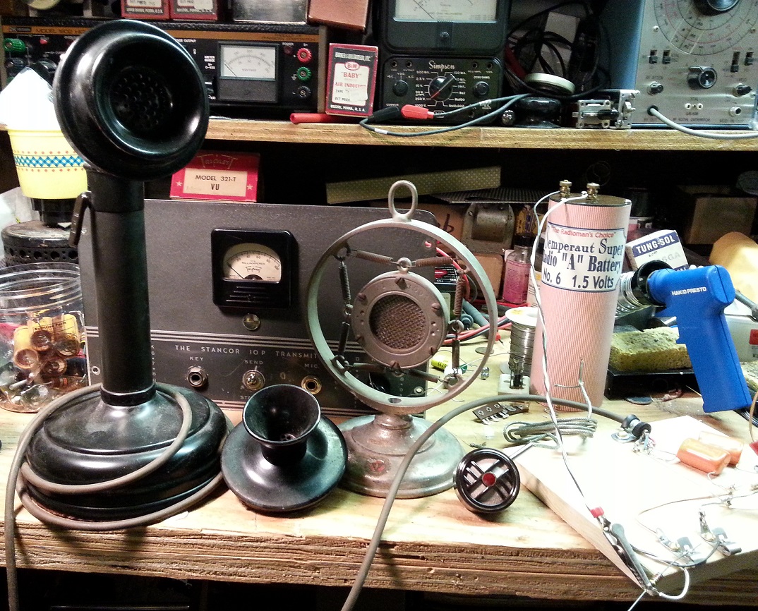
     I met my dear old friend Don H., and several other people I know slightly, including the talented Jim Borgioli,whose ham work includes building very nice AM transmitters that run at or near the legal power limit. And one ham who knew me!  A young man who'd gone looking for info on the Stancor 10-P transmitter and found my postings about it on Retrotchnologist walked up to me in the flea market area, asked, "Are you Roberta?" and introduced himself.

     Found but missed a nice balanced antenna tuner.  I should have purchased it at first sight!  But it's a cloneable design and I think I have the parts.

     A fun time!  When I returned home, the phone tech was there -- and pointed out a very large broken limb on the roof and my ham antenna and still loosely attached to the tree.  I climbed up and had a look, but it's too big and too precarious for me.  We've called the singing tree hippie, who does great work at a fair price.

Monday, June 1, 2015

CARBON MICROPHONE CHECKING

     I went through most of my collection of carbon mics tonight.  The old ones are nearly always non-working when found: they pick up humidity, the carbon packs solid, and that's it; or the carbon granules dribble out over time. 

     Not all of them.  I found several that still work, and a couple that I'd thought were dead (a Shure Brothers 3-A and a 3-B) aren't.  Here are the working ones:
      Two are telephone-types, the T-32 (a pretty common desk mic around WW II) and an odd old telco one from the wood-wall and candlestick era next to it.  The Universal X1 in its nice stand was a complete surprise; I assumed from condition it was a goner.  Nope!  And the little Philmore lapel mic next to it had been sealed up.  The Stancor 10-P -- which needs a carbon mic to do AM -- is behind them.

     Here's my test set-up.  The mic cable goes to a little mixer.  It's isolated with 0.68 uF series condensers, looking at current across a 150 Ohm resistor in series with the mic, a 1.5 V battery and an added resistor to limit current -- I used 820 Ohms and it worked okay for checking.  In practice, you trim microphone current for best fidelity with a carbon -- usually the lower, the better, but there's a point where it stops working.
     Mic cable to mixer at left, connections to carbon mic under test at top right, battery terminals and added current-limiting resistor at bottom right.  I think you can trace it from the photo.

Thursday, March 26, 2015

STANCOR 10P TRANSMITTER: UPDATE 12

     A very long time in coming, I did make progress on the Stancor 10P, getting as far as power supply:

     Rectifier heaters and HV, filter caps, filter choke and bleeder.  It's a little crowded and I struggled to solder the capacitor and resistor to the chassis, even with the big iron.

     That work had it almost done, so tonight I added a few more things:
     Installed output feedthroughs and connected the output, wired up the primary power and the meter.

     Top view:

     Rear view:

     Front view:
     Initial tests -- just power-up, check for excessive current draw, check B+ -- went okay.  Hoping to try more by the weekend.

     Update: Tuned the transmitter up on 40m with a 100 Watt lamp in series, and it made a little power (4:1 balun to a Bird Wattmeter and 50 Ohm load.  Tried it without the lamp and blew the fuse instantly.  So....bigger fuse, and/or 150 and 200W lamps.  Maybe a little Amprobing..

     Update 25 May: Yesterday, I finally brought the transmitter up without a light bulb in series with the 120V AC and it worked. Last time I tried this with the wrong fuse (fast-blow) and it popped immediately -- at which point, I set the transmitter aside for awhile. I didn't have the balun and wattmeter for this test, just a 40W light bulb across the output, which is a bit low-resistance for the link coupling to match to. Plenty more to do but this was a big step.

Thursday, January 29, 2015

YANKEE RADIO TOOL KIT, #106

     Some time ago, I chanced on a nice Yankee No. 100 tool set.  Readers suggested I keep watch for a No. 106 boxed set of "radio tools," which, other than a soldering iron or copper, contains about everything you'd need to build a 1920s-type radio -- and is plenty useful on later equipment.
     I have seen a few come and go at princely prices, including a lovely store display version.  They are fine tools but not on my budget.  Or not until some months ago, when a slightly-grubby one showed up on a well-known auction site.  The serious collectors weren't after it but many of the tools were there; it was hard to figure out what was going on with the little drill, which appeared to have been taken apart.  The wooden case is the most difficult part to find -- the No. 105 kit offered all the tools except the drill, at half the price and in a cardboard box -- and the case was certainly there.
     It arrived in disappointingly worse shape than the original listing showed, due to a poor packing job.  Adjustments, as they say, were made.
     The mystery of the disassembled drill was simple enough: it was the wrong drill.  This proved no hardship; the little Yankee "Radio Drill," No. 1431, is commonly found and inexpensive.

     At present, I am repairing the case, starting with the badly cracked bit holder.  The two long screwdriver blades are missing, as is the uncommon Ratchet Tool Holder No. 230.  They may be a very long while in the finding.
     The incorrect drill is nevertheless a treat: a No. 1530 Ratchet Drill, which can be set to operate in five different modes: plain, left-handed ratchet, right handed ratchet, right-hand double, or locked.  The last is handy when tightening or loosening the chuck, the simple ratchet modes only respond to one direction of turning the crank -- but "double" turns the chuck clockwise no matter which way the crank is turned!