
 Front view (tomcat left in for scale). The 40m coil is installed.
Under chassis view (tomcat as per above) -- the chewed-up resistor is a 100 mA shunt across the (actually) 1 mA/1V/1k meter. You didn't really think it was a 4-Ampere meter, did you? It's salvaged from an old commercial rig. If you look carefully, you can see the insulator the 140 pF variable is mounted on.

Close-up of the front.
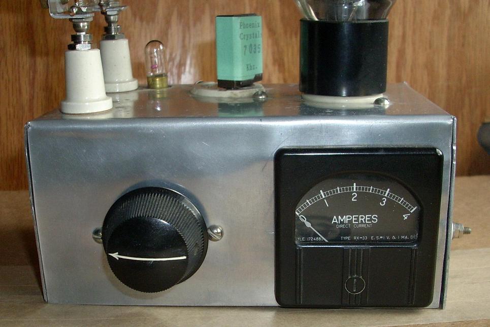 The crystal is one of a batch I purchased from Phoenix Crystals, which was one of the very last of the small crystal grinders. Sadly, the owner passed away about ten years ago and no buyer could be found for the business.
Changes from the original Fred Sutter transmitter are few:
1. I used a male chassis connector for the power supply. --These days, I'd use an octal, as the "tube base" pattern 4, 5, 6 and 7-prong plugs (though not tube sockets) are no longer made.
2. The crystal is an FT-243 rather than a "doorknob" type and the socket is according different. You could use a 2-prong socket for the crystal if you had one, but they'll fit an octal tube socket okay. (There's a no-wrong-way-to-plug-in wiring pattern for FT-243's in an octal socket. I didn't use it but I'll look it up and post it if any reader is curious.)
3. I should have used enameled wire for the coils. What I did use is #14 house-wire, stripped. This increases the hazard, since the coil is at B+ potential. (Now that I own a drill press, I can redo them properly.) The material holding them is clear plastic rather than black Bakelite. --But that is real Duco glue holding it all together!
4. The meter is different, a square one instead of the round version he used (probably a Triplett and a bit nicer than the Readrite typical of low-end designs at the time). It was the right size and I had several.


