T. R. McElroy was a blazing fast telegrapher -- any code, any time. He worked both landline and radiotelegraphy, and set speed records.
But he was ambitious, too. In the 1930s, he started manufacturing semiautomatic telegraph keys of his own design, massive, heavy bugs that suited his own style -- and which appealed to plenty of others, too.
The original Mac bugs were heavy, rectilinear keys with their own style, a little "Arts & Crafts meet heavy industrial" look. But the times --and the styles -- were changing and shortly before WW II, Mac introduced a series of streamlined telegraph keys unlike any any other, culminating in the S-600 Super Streamspeed semiautomatic key, possibly the most graceful "bug" ever made.
I own a few Mac keys and recently bought an accessory:
There's an uncommon Bakelite-based Streamkey at far left, followed by a Telegraph Apparatus Co. (not Inc.) copy* of the wrinkle-finished metal-base Streamkey (you can tell by the bulge in the lever arm at the contact area) and a pair of chrome-plated McElroys. The Streamspeed is at far right, and it handles just as fast and sleek as it looks. At the very back, the accessory and its box: an Oscillatone code-practice oscillator. They are not especially rare and this one was offered at a very low price -- how could I pass it up?
Restoration will be interesting. The Bakelite is likely to be very brittle.
There are still McElroys in the electronics business. They're not making telegraph keys any more, but the name lives on.
________________________________
* TACo was a co-venture between McElroy and Hallicrafters. They built copies of Mac Streamkeys and their own interesting semiautomatic key, sometimes known as the "hole-in-the-wall" bug.
Showing posts with label TELEGRAPHY. Show all posts
Monday, February 15, 2016
Thursday, March 26, 2015
STANCOR 10P TRANSMITTER: UPDATE 12
A very long time in coming, I did make progress on the Stancor 10P, getting as far as power supply:
Rectifier heaters and HV, filter caps, filter choke and bleeder. It's a little crowded and I struggled to solder the capacitor and resistor to the chassis, even with the big iron.
That work had it almost done, so tonight I added a few more things:
Installed output feedthroughs and connected the output, wired up the primary power and the meter.
Top view:
Rear view:
Front view:
Initial tests -- just power-up, check for excessive current draw, check B+ -- went okay. Hoping to try more by the weekend.
Update: Tuned the transmitter up on 40m with a 100 Watt lamp in series, and it made a little power (4:1 balun to a Bird Wattmeter and 50 Ohm load. Tried it without the lamp and blew the fuse instantly. So....bigger fuse, and/or 150 and 200W lamps. Maybe a little Amprobing..
Update 25 May: Yesterday, I finally brought the transmitter up without a light bulb in series with the 120V AC and it worked. Last time I tried this with the wrong fuse (fast-blow) and it popped immediately -- at which point, I set the transmitter aside for awhile. I didn't have the balun and wattmeter for this test, just a 40W light bulb across the output, which is a bit low-resistance for the link coupling to match to. Plenty more to do but this was a big step.
Rectifier heaters and HV, filter caps, filter choke and bleeder. It's a little crowded and I struggled to solder the capacitor and resistor to the chassis, even with the big iron.
That work had it almost done, so tonight I added a few more things:
Installed output feedthroughs and connected the output, wired up the primary power and the meter.
Top view:
Rear view:
Front view:
Initial tests -- just power-up, check for excessive current draw, check B+ -- went okay. Hoping to try more by the weekend.
Update: Tuned the transmitter up on 40m with a 100 Watt lamp in series, and it made a little power (4:1 balun to a Bird Wattmeter and 50 Ohm load. Tried it without the lamp and blew the fuse instantly. So....bigger fuse, and/or 150 and 200W lamps. Maybe a little Amprobing..
Update 25 May: Yesterday, I finally brought the transmitter up without a light bulb in series with the 120V AC and it worked. Last time I tried this with the wrong fuse (fast-blow) and it popped immediately -- at which point, I set the transmitter aside for awhile. I didn't have the balun and wattmeter for this test, just a 40W light bulb across the output, which is a bit low-resistance for the link coupling to match to. Plenty more to do but this was a big step.
Saturday, May 17, 2014
TELEGRAPH KEYS AT 2014 DAYTON HAMVENTION
A selection of old keys -- and one new one -- from the Dayton Hamvention:
"Pendograph," with a base-supported vertical pendulum for forming dits.
Pendograph close-up. The owner let me try it -- very nice feel. It's a
"release of tension" design like the Mecograph: the reed is flexed at
rest, and released to vibrate when you work the left paddle.
"Automorse," an Australian-made fully-automatic mechanical key.
Full-auto for International Morse, as used on radio, anyway: the third
paddle is for the long dahs of landline Morse, and that's manual.
This is a Mecograph, one of two versions.
The original machine for live coverage of news -- cut into the nearest telegraph wire and get to sending! You see these in old photos of press coverage of sporting events and Presidential appearances.
Sounders!
A full-auto, all-mechanical key built by Indy's own brilliant Richard Meiss. He knows more about the physics of bug keys than any man alive. This key is palm-sized, and uses a mechanically-varied mass to switch between dits and dahs.
![]() |
![]() |
![]() |
![]() |
![]() |
![]() |
![]() |
Friday, November 15, 2013
W9BSP: A HAM'S HAM, A TEACHER'S TEACHER
His name was Marshall H. Ensor. He was a shop teacher in Olathe, Kansas; except for a stint traning radiomen during WW II, he spent most of his life there. He spent it talking to the world and not just idle chatter, either -- Marshall Ensor (and his sister Loretta) spent evenings sending code practice and "teaching radio by radio," a free-for-the-listening lecture course over the powerful W9BSP - W9UA transmitter.
I'd read all this in back issues of ARRL's magazine QST. What I didn't know is the house where they lived is now a museum and the grounds around it are a park. That big transmitter, in its fine-furniture cabinet, is back on the air again.
As a shop teacher, he reached thousands. There's no way to know how many people, all over the world, he taught about radio. Tens of thousands? (This modest man admitted in a resume sent to the U. S. Navy, "Reputed to have trained more radio operators than any other individual in the United States.") And all from a farmhouse in Kansas.
I'd read all this in back issues of ARRL's magazine QST. What I didn't know is the house where they lived is now a museum and the grounds around it are a park. That big transmitter, in its fine-furniture cabinet, is back on the air again.
As a shop teacher, he reached thousands. There's no way to know how many people, all over the world, he taught about radio. Tens of thousands? (This modest man admitted in a resume sent to the U. S. Navy, "Reputed to have trained more radio operators than any other individual in the United States.") And all from a farmhouse in Kansas.
Thursday, October 10, 2013
STANCOR 10P TRANSMITTER: PART 10
I made some impressive-looking progress this afternoon and stopped to photograph it because it's an example of a technique not everyone knows about: prewiring.
There are a number of controls and jacks mounted on the front panel and it's a pretty tight fit. Rather than mount them and try to get into a small space with needlenose pliers, soldering iron and solder, I wired up the most challenging (a multi-contact jack and a toggle switch) on the bench, and connected the input transformer to the microphone jack before installing it.
This results in quite a few wires cut a little longer than necessary. Yes, there will be some waste and yes, they sell that stuff by the foot, but how much does frustration cost? By color-coding them, it it's easier to sort them out -- blue is plate return, red is B+, gray is cathode and switched ground, and black is ground, which are (mostly) old-time standard colors.
The audio level control remains to be wired up and put in. It mounts right in front of the rectifier tube, so lead dress will be important. You can see the shielded lead from the mic transformer headed over to the empty hole in the front panel; another shielded wire will return from the control to the grid of the modulator tube.
I had a bad moment when I realized I don't own a 1/2" Spintite driver to tighten the nuts of the 1/4" jacks. But I do have a perfectly good modern Klein nutdriver that size.
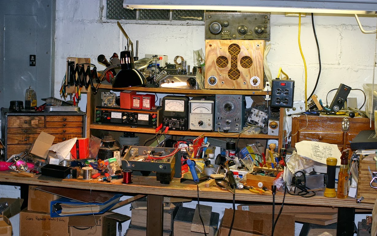
My workbench is a little chaotic at present.
As usual, tools have outstripped tool storage and projects have grown to take up the available space. There's everything from the remains of an old soldering-iron control box and a balanced-line transmit-receive switch that didn't work out (not enough power supply for the relay!) to my QSL-40 transmitter, a box of pegboard hooks and big piece of un-etched PC board. Somewhere over on the left is a jack box for the CW transmitters (half of them have the key jack on the back, some have heathen connectors that decent folk would never use instead of proper 1/4" two-circuit jacks) and a narrow audio filter.
![]() |
| Photo is very large if you click on it |
This results in quite a few wires cut a little longer than necessary. Yes, there will be some waste and yes, they sell that stuff by the foot, but how much does frustration cost? By color-coding them, it it's easier to sort them out -- blue is plate return, red is B+, gray is cathode and switched ground, and black is ground, which are (mostly) old-time standard colors.
The audio level control remains to be wired up and put in. It mounts right in front of the rectifier tube, so lead dress will be important. You can see the shielded lead from the mic transformer headed over to the empty hole in the front panel; another shielded wire will return from the control to the grid of the modulator tube.
I had a bad moment when I realized I don't own a 1/2" Spintite driver to tighten the nuts of the 1/4" jacks. But I do have a perfectly good modern Klein nutdriver that size.
My workbench is a little chaotic at present.
As usual, tools have outstripped tool storage and projects have grown to take up the available space. There's everything from the remains of an old soldering-iron control box and a balanced-line transmit-receive switch that didn't work out (not enough power supply for the relay!) to my QSL-40 transmitter, a box of pegboard hooks and big piece of un-etched PC board. Somewhere over on the left is a jack box for the CW transmitters (half of them have the key jack on the back, some have heathen connectors that decent folk would never use instead of proper 1/4" two-circuit jacks) and a narrow audio filter.
Tuesday, July 23, 2013
JOHNSON VIKING CHALLENGER: INDY HAMFEST SWAG, PART FIVE
E.F. Johnson built a wide range of amateur radio transmitters (among other things), starting in the 1920s. They hit their stride with the postwar ham radio boom and continued through the early days of SSB. Every last one of the postwar rigs was a "Viking" something-or-other, which I suppose isn't a huge surprise for a company based in Waseca MN, up there where the descendants of Vikings farmed the land. The first two, delightful behemoths, were the Viking I and Viking II, but after that, there were Adventurers, Rangers, Navigators, Invaders(!) and the Challenger:
There was one on a table at the Indy Hamfest, priced over $100 (a bit high, I thought) but the guy was starting to pack up and when he noticed my interest, suggested the price was highly negotiable. I named a rather low one and he was okay with it -- even added a microphone.
It's a CW/AM rig, the latter provided by screen-modulating a couple of TV sweep tubes (6DQ6) with a miniature beam tetrode audio tube (6AQ5). One does not expect high fidelity from this kind of arrangement but given a decent load, it should be adequate.
The knobs for bandswitch, "excitation" (grid drive) and mode switch are notably missing pointers to tell you where they're set. The originals were sort of subtle, white plastic pieces glued in at the bottom of the knobs, and I'll have to work out a replacement.
Does it work? The seller claimed it did -- it's got Johnson's poorly-documented "push to talk" modification (no schematic, just a step-by-step and partial pictorial) and a connections-unknown mic socket, so I'll want to trace all that out first, clean it up and then, perhaps, power it up via The Gadget.
What's The Gadget? That's a post for another time!
There was one on a table at the Indy Hamfest, priced over $100 (a bit high, I thought) but the guy was starting to pack up and when he noticed my interest, suggested the price was highly negotiable. I named a rather low one and he was okay with it -- even added a microphone.
It's a CW/AM rig, the latter provided by screen-modulating a couple of TV sweep tubes (6DQ6) with a miniature beam tetrode audio tube (6AQ5). One does not expect high fidelity from this kind of arrangement but given a decent load, it should be adequate.
The knobs for bandswitch, "excitation" (grid drive) and mode switch are notably missing pointers to tell you where they're set. The originals were sort of subtle, white plastic pieces glued in at the bottom of the knobs, and I'll have to work out a replacement.
Does it work? The seller claimed it did -- it's got Johnson's poorly-documented "push to talk" modification (no schematic, just a step-by-step and partial pictorial) and a connections-unknown mic socket, so I'll want to trace all that out first, clean it up and then, perhaps, power it up via The Gadget.
What's The Gadget? That's a post for another time!
Sunday, July 21, 2013
INDY HAMFEST SWAG, PART THREE
A "what-is-it?" box. I was pretty sure I knew...
...Inside, a power transformer, top-hat diode, a lot of R and C and a relay (not visible in this photo) suggested what it might be. Two pots and a three-circuit jack on the front were a clue. A pair of insulated screw terminals on the back, marked "S" and "T" were the final giveaway: it's an all-passive-component automatic code keyer! The two pots are for speed and "weight," the timing ratio between dits (dots) and dahs (dashes).
For $3.00, it's a good steel minibox and a handful of probably-useful components.
Elsewhere -- and I should have bought more from the guy, he had a bunch of knobs and dials -- this gadget:
Just a calibrated knob, you say? Have a look at the other side!
It's a nice old vernier dial, made by Crowe up in Chicago. (You can just read "CRO..." behind the drive at the lower center-left.) They've been gone for decades but their knobs and dials, etc. still show up. It's good stuff. Paid a couple of bucks. (The one mounting leg that looks broken was made that way. I don't know why.) It needs a little fixed scale to be a true "vernier" dial and I may have one the right size.
...Inside, a power transformer, top-hat diode, a lot of R and C and a relay (not visible in this photo) suggested what it might be. Two pots and a three-circuit jack on the front were a clue. A pair of insulated screw terminals on the back, marked "S" and "T" were the final giveaway: it's an all-passive-component automatic code keyer! The two pots are for speed and "weight," the timing ratio between dits (dots) and dahs (dashes).
For $3.00, it's a good steel minibox and a handful of probably-useful components.
Elsewhere -- and I should have bought more from the guy, he had a bunch of knobs and dials -- this gadget:
Just a calibrated knob, you say? Have a look at the other side!
It's a nice old vernier dial, made by Crowe up in Chicago. (You can just read "CRO..." behind the drive at the lower center-left.) They've been gone for decades but their knobs and dials, etc. still show up. It's good stuff. Paid a couple of bucks. (The one mounting leg that looks broken was made that way. I don't know why.) It needs a little fixed scale to be a true "vernier" dial and I may have one the right size.
Thursday, June 6, 2013
THE FIRST PLAY-BY-PLAY MAN
In fact, he probably invented the idea. And he was a Hoosier.
...It was The Big Game -- and not a home game for his school's team. The year was 1903. University of Michigan student, Indiana resident (and part-time telegrapher) Floyd J. "Jack" Mattice had already dreamed up (and sold to Western Union!) the notion of having sports-knowledgeable telegraphers transmit moment-by-moment scores and high points directly, instead of waiting on copy from print reporters and now he'd come up with another idea: a long-distance telephone line. He'd describe the game to the other students back at UM as it happened.
Bell Telephone installed a phone booth on 40-foot poles along the sidelines at mid-field and a direct line back to the auditorium at UM. Shortly before the game began, Mattice climbed up and placed the call--
But remember, this is 1903. Electrical amplification is still several years away. Backstage, ten more sports-fan students were listening in, each one in turn memorizing a few minutes' play and rushing onstage to relay it to the audience, and then back to his listening post as the next "sportscaster" took over, on after another.
It was a popular notion. At UM, the practice continued until radio broadcasting took over in the 1920s. As for Mattice, he had another career; you see, he'd arrived at college already a member of the bar. After graduation, he went home to Rochester and practiced law, serving a couple terms as county prosecutor. Even that wasn't enough -- during WW I, he went to work for the Bureau of Investigation's office in Indianapolis and then at the U. S. District Attorney's office. He went back into private practice a few years later and then served in various posts with the city, then back to Federal work during WW II, ending up as a prosecutor at the war crimes trials in Japan.
Still, inventing sportscasting probably made more people happy than any of his legal work. He retired to Rochester and passed away in 1971. He maintained a lifelong interest in telegraphy and if you've ever wondered about the curious number of attorney/sportscasters (Howard Cosell, for instance), while I don't think Mr. Mattice can be blamed for it, he was certainly one of the first examples.
(Crossposted from my personal/political blog.)
...It was The Big Game -- and not a home game for his school's team. The year was 1903. University of Michigan student, Indiana resident (and part-time telegrapher) Floyd J. "Jack" Mattice had already dreamed up (and sold to Western Union!) the notion of having sports-knowledgeable telegraphers transmit moment-by-moment scores and high points directly, instead of waiting on copy from print reporters and now he'd come up with another idea: a long-distance telephone line. He'd describe the game to the other students back at UM as it happened.
Bell Telephone installed a phone booth on 40-foot poles along the sidelines at mid-field and a direct line back to the auditorium at UM. Shortly before the game began, Mattice climbed up and placed the call--
But remember, this is 1903. Electrical amplification is still several years away. Backstage, ten more sports-fan students were listening in, each one in turn memorizing a few minutes' play and rushing onstage to relay it to the audience, and then back to his listening post as the next "sportscaster" took over, on after another.
It was a popular notion. At UM, the practice continued until radio broadcasting took over in the 1920s. As for Mattice, he had another career; you see, he'd arrived at college already a member of the bar. After graduation, he went home to Rochester and practiced law, serving a couple terms as county prosecutor. Even that wasn't enough -- during WW I, he went to work for the Bureau of Investigation's office in Indianapolis and then at the U. S. District Attorney's office. He went back into private practice a few years later and then served in various posts with the city, then back to Federal work during WW II, ending up as a prosecutor at the war crimes trials in Japan.
Still, inventing sportscasting probably made more people happy than any of his legal work. He retired to Rochester and passed away in 1971. He maintained a lifelong interest in telegraphy and if you've ever wondered about the curious number of attorney/sportscasters (Howard Cosell, for instance), while I don't think Mr. Mattice can be blamed for it, he was certainly one of the first examples.
(Crossposted from my personal/political blog.)
Sunday, May 19, 2013
DAYTON HAMVENTION 2013
"Turk" Turon and I were at the Dayton Hamvention the better part of Friday and we saw about half. It was amazing. I passed up an early Globe transmitter -- next step smaller than the Globe King. Shoulda, woulda-- Could not lift it. Priced to move at $300 and in working condition. Oh, if only!
(I did manage a smaller/newer rig, a Heathkit DX-60, also said to be working. We'll see.)
Some rigs were way too big to move:
Love that paint-job! (Here's a closer look.)
This is the RF side; audio is the same size, with two more final-stage tubes and a nice window to enjoy them through. Be sure to tune for minimum meltage.
It's a Gates 1kW job, and very large for its size; but that just makes it easier to work on. There was a Collins 20V in front of it, of which I hope to post pictures later. Notice the bead-chain drive crossing the window? The output tuning network is on the right side of the cabinet -- but Gates did't want all the knobs over there, that wouldn't be balanced! So they extended it. That means you'll be retuning a bit after start-up until cabinet temperature stabilizes: all that extra mechanical folderol carries a price. The 20V has much the same trick, only with brass bead-chain, aluminum drive wheels and a steel cabinet, all mounted high up in a physically-smaller transmitter at the same power level, or, "Please touch up Loading adjustment once an hour until noon," as the note at one station read; they only ran the 20V one day a week and it woke slowly.
Some hair was movingly big.
Kristen had admirers wherever she went.
Table of Vibroplexes.
The new owner is just out of the shot. Have I mentioned how good Vibroplex parts support is these days? It is and you can thank him for it.
Turk found a man-sized soldering copper.
Well, more like statue-sized. When they build the Radio Row monument in NYC, it'll be holding one of those, looking out at Lady Liberty as if wondering about asking to borrow the torch.
(I did manage a smaller/newer rig, a Heathkit DX-60, also said to be working. We'll see.)
Some rigs were way too big to move:
Love that paint-job! (Here's a closer look.)
This is the RF side; audio is the same size, with two more final-stage tubes and a nice window to enjoy them through. Be sure to tune for minimum meltage.
It's a Gates 1kW job, and very large for its size; but that just makes it easier to work on. There was a Collins 20V in front of it, of which I hope to post pictures later. Notice the bead-chain drive crossing the window? The output tuning network is on the right side of the cabinet -- but Gates did't want all the knobs over there, that wouldn't be balanced! So they extended it. That means you'll be retuning a bit after start-up until cabinet temperature stabilizes: all that extra mechanical folderol carries a price. The 20V has much the same trick, only with brass bead-chain, aluminum drive wheels and a steel cabinet, all mounted high up in a physically-smaller transmitter at the same power level, or, "Please touch up Loading adjustment once an hour until noon," as the note at one station read; they only ran the 20V one day a week and it woke slowly.
Some hair was movingly big.
Kristen had admirers wherever she went.
Table of Vibroplexes.
The new owner is just out of the shot. Have I mentioned how good Vibroplex parts support is these days? It is and you can thank him for it.
Turk found a man-sized soldering copper.
Well, more like statue-sized. When they build the Radio Row monument in NYC, it'll be holding one of those, looking out at Lady Liberty as if wondering about asking to borrow the torch.
Thursday, March 7, 2013
TINY MORSE KEY
In years past, J. H. Bunnell (the firm that developed the standard form of straight key used in North America) has occasionally done production runs of the miniature telegraph key they first manufactured as a souvenir for the 1905 reunion of the Old Time Telegraphers' Association; at some point, Bunnell even made a tiny sounder as well. No mere watch-fob, both items work.
Bunnell is not the only maker of very small, "Triumph"-pattern telegraph keys. KA6IRL made "QRP J-38" keys for several years and when one showed up at a well-known auction site, I was the winning bidder.
Here it is between two full-sized keys. Just the thing for when you only want a short QSO or smalltalk!
Bunnell is not the only maker of very small, "Triumph"-pattern telegraph keys. KA6IRL made "QRP J-38" keys for several years and when one showed up at a well-known auction site, I was the winning bidder.
Here it is between two full-sized keys. Just the thing for when you only want a short QSO or smalltalk!
Labels:
RADIO,
TELEGRAPHY
Thursday, November 1, 2012
DIME KEY
In the far-off past when radio was nearly all Morse code (what's that Fessenden fellow on about?), everybody keyed fairly high currents in the primary side of big transmitters, especially spark rigs. Commercial stations used big, purpose-built keys or keying relays. Hams....improvised.
One key, two silver dimes and a nice big soldering copper (or electric soldering iron). Add amateur ingenuity.
Real dimes! (Filed flat. Honest, Mr. T-man, I didn't do it!)
This example was found on Etsy. "Dime keys" are often fakes; this one, the key's an older type, the solder looks like the old-time stuff, the dimes are sure-enough silver and the knob bears an "Aug 3, 1920" patent date; a little late but not too late. So it's probably the real deal.
One key, two silver dimes and a nice big soldering copper (or electric soldering iron). Add amateur ingenuity.
Real dimes! (Filed flat. Honest, Mr. T-man, I didn't do it!)
This example was found on Etsy. "Dime keys" are often fakes; this one, the key's an older type, the solder looks like the old-time stuff, the dimes are sure-enough silver and the knob bears an "Aug 3, 1920" patent date; a little late but not too late. So it's probably the real deal.
Labels:
RADIO,
TELEGRAPHY
Tuesday, May 29, 2012
THE WINDOM
The G5RV -- more of a "bent extended double Zepp," which I think Varney would have disavowed -- I use doesn't load up well on 40 meters. It's been arranged to fit the available space and it's just not that good a match.
I don't worry much -- if you can get some energy into your antenna, it'll work even with lousy SWR -- but it was pretty bad.
So I put up an off-center-fed 40 m dipole, a sort of a coax-fed Windom.* With the feedpoint at the 80%/20% point, it should look close to 200 Ohms and take a 4:1 transformer to present a decent match to 50 Ohms.
The antenna part is easy enough -- take 67' of wire and divide accordingly, then make it fit (I ended up having to bend both ends).
The transformer... It was a holiday. The ham store we haven't got was closed. But all you really need is wire and a coil form (PVC pipe) and a little hardware:
(The branch is not really that close to it.) Ended up with 11 bifilar turns of #14 house wire on approximately 1- 1/2" diameter PVC. Hams get all worked up over these but with about three bucks of materials in it, this version is not too painful to have to redo from scratch if the first try doesn't work. My design is all rule-of-thumb and fudge-factored from other versions on the Web.
Here's a funny angle on the transformer and one of the bends:
It's about 20' up at the highest points.
Finished it after dark -- I'd installed a coax feedthrough but had to put the connectors on the coax -- and had a QSO within minutes of getting on the air. (Real DX: Warsaw, IN) And it tunes up on 40 meters just fine!
______________________________
* Loren G. Windom, W8GZ, yet another of the antenna-designing hams from Columbus, OH. You may have heard of the other one -- W8JK, John Krause, of the 8JK HF beam and the helical antenna (both modes!).
I don't worry much -- if you can get some energy into your antenna, it'll work even with lousy SWR -- but it was pretty bad.
So I put up an off-center-fed 40 m dipole, a sort of a coax-fed Windom.* With the feedpoint at the 80%/20% point, it should look close to 200 Ohms and take a 4:1 transformer to present a decent match to 50 Ohms.
The antenna part is easy enough -- take 67' of wire and divide accordingly, then make it fit (I ended up having to bend both ends).
The transformer... It was a holiday. The ham store we haven't got was closed. But all you really need is wire and a coil form (PVC pipe) and a little hardware:
Here's a funny angle on the transformer and one of the bends:
Finished it after dark -- I'd installed a coax feedthrough but had to put the connectors on the coax -- and had a QSO within minutes of getting on the air. (Real DX: Warsaw, IN) And it tunes up on 40 meters just fine!
______________________________
* Loren G. Windom, W8GZ, yet another of the antenna-designing hams from Columbus, OH. You may have heard of the other one -- W8JK, John Krause, of the 8JK HF beam and the helical antenna (both modes!).
Labels:
RADIO,
TELEGRAPHY
Saturday, April 14, 2012
BUG RACING
Actually, it's an exhibition, not a contest of speed. My three Vibroplex No. 4 or Blue Racer bugs of varying vintage:
L. to R, pre WW II, with a U-damper and "cloverleaf" frame; 1946, with scaled-down "Original" style upperworks; a 2001 "Millennium Bug" with full-scale mechanicals on a small base.
From the front, the frame differences are clear:
The damper variations show in the rear view:
The oldest one had obviously been dropped and was green and nasty with corrosion when purchased. I replaced the thumbpiece and straightened the frame gently, enough so it would function. The reed (flat spring) had been deeply filed by a prior owner, an old trick to slow 'em down:
The very oldest ones had smooth blue-enamelled bases, probably with the gold-pinstriping treatment; my oldest probably dates from 1921 through '41 but without the nameplate (long gone), I don't think it can be narrowed down any more than that.
They all work pretty well. The 2001 bug has a "bug tamer" extension on the pendulum to slow it down. I'd like to add a "Vari-Speed" to the '46 De Luxe (sold here, scroll down for a video link of the gadget in action), and give that a try. The oldest one, with the filed reed and massive pendulum weight, is already just about right.
L. to R, pre WW II, with a U-damper and "cloverleaf" frame; 1946, with scaled-down "Original" style upperworks; a 2001 "Millennium Bug" with full-scale mechanicals on a small base.
From the front, the frame differences are clear:
The damper variations show in the rear view:
They all work pretty well. The 2001 bug has a "bug tamer" extension on the pendulum to slow it down. I'd like to add a "Vari-Speed" to the '46 De Luxe (sold here, scroll down for a video link of the gadget in action), and give that a try. The oldest one, with the filed reed and massive pendulum weight, is already just about right.
Monday, April 2, 2012
1946 De Luxe Vibroplex Blue Racer
In 1946, the year's production count still included the famous "Lightning Bug" derived J-36 military speed key built by Vibroplex. (Other firms, including Lionel, made J-36s, too.) All told, the company made over 4200 bugs that year, but only a fraction of that number were Blue Racers -- and only a fraction of those were all-chrome "De Luxe" models like my recent purchase.
In fact, from 1943 to '45, you couldn't even get a De Luxe with a chromed base: as a war measure, Vibroplex used battleship gray paint instead. It wasn't only Technicolor red that went to war.
By '46, chrome was back:
And how! This is an early version of the De Luxe, with a conventional-looking upper pivot screw and jam nut, but that's a jeweled bearing and there another one for the lower pivot. The cord and wedge, properly tied off at the binding posts, is a nice touch and marks this key as likely to have been originally owned by a professional telegrapher -- the wedge allows the key the "plug in" to the employer-provided straight key (screwed down to the operating table) without making any modifications or disconnecting any wires. (Landline telegraphy is a series system: unhook any part of it and the whole line is out of service; so they tended to frown on it.)
The owner took care to mark the carrying case...
...Which isn't the official Vibroplex version, but a cut-down cheese box from a well-known cheesemonger!*
Price? $150, a fair deal for a key of this age, condition and with the cord and wedge.
_________________________
* At last, a chance to use the word in a non-pejorative sense!
In fact, from 1943 to '45, you couldn't even get a De Luxe with a chromed base: as a war measure, Vibroplex used battleship gray paint instead. It wasn't only Technicolor red that went to war.
By '46, chrome was back:
Price? $150, a fair deal for a key of this age, condition and with the cord and wedge.
_________________________
* At last, a chance to use the word in a non-pejorative sense!
Thursday, February 23, 2012
WOBBLY MORSE CODE
Good for me, I actually used my ham rig and had a nice (but short) CW conversation.
...Oh, it was short. My semiautomatic telegraph key, a Vibroplex Blue Racer 2000 (their "Millenium Bug") was really uncooperative. I didn't realize why until after the QSO was over: the speed is set by a weight; the weight is held by a little thumbscrew...and I had not tightened it. Therefore, it had fallen out. So as I sent, the weight wobbled. This made forming the letters and numbers very tricky!
Better luck next time. I really should make up an extension jack panel for the transmitters -- there's half a dozen keys on my operating desk and if the jack was easily reached, changing from one to another would be easy.
...Oh, it was short. My semiautomatic telegraph key, a Vibroplex Blue Racer 2000 (their "Millenium Bug") was really uncooperative. I didn't realize why until after the QSO was over: the speed is set by a weight; the weight is held by a little thumbscrew...and I had not tightened it. Therefore, it had fallen out. So as I sent, the weight wobbled. This made forming the letters and numbers very tricky!
Better luck next time. I really should make up an extension jack panel for the transmitters -- there's half a dozen keys on my operating desk and if the jack was easily reached, changing from one to another would be easy.
Sunday, January 29, 2012
VIBROPLEX, OUCH!
It appears that the Vibroplex Co., under new ownership in Knoxville, TN (and with, last I checked, a lot of repair parts and accessories back in production), has made a radical change to the nameplate.
I think it is an unfortunate change. Given the cost of replacing the dies that stamped the old nameplates, going to a printed or silkscreened label may have been inevitable, but the design is terribly plain and a bit jarring to my eye.
It is, however, a lot better than not having Vibroplex around any more.
Remember, the earliest Vibroplex keys had very plain serial-number plates instead of the ornate stamped ones we've become used to -- and, in some cases, a water-slide decal of the "bug" logo.
I think it is an unfortunate change. Given the cost of replacing the dies that stamped the old nameplates, going to a printed or silkscreened label may have been inevitable, but the design is terribly plain and a bit jarring to my eye.
It is, however, a lot better than not having Vibroplex around any more.
Remember, the earliest Vibroplex keys had very plain serial-number plates instead of the ornate stamped ones we've become used to -- and, in some cases, a water-slide decal of the "bug" logo.
Monday, October 17, 2011
COINCIDENCE
Radio hams may be a little surprised to learn the paddlewheel steamer USS C. W. Morse, used by the Navy as a receiving ship in WW I, did not specialize in radiomen. Who was C. W. Morse? I don't know. A cursory websearch finds only the ship.
Labels:
RADIO,
TELEGRAPHY
Wednesday, April 20, 2011
WE'RE ALL NOVICES NOW
Ever since the FCC dropped the higher-speed code requirements, some of the nicer touches of operating procedures for CW have become a bit more difficult to pick up.
Of course, they were never that simple to come by. Bad habits tend to sprawl. Back when John Huntoon edited QST, he printed an article by W6DTY* that summarizes good operating without being stuffy or too preachy. It went over well enough that ARRL reprinted it as a handout and sent it to new hams; and now, YOUR NOVICE ACCENT And What To Do About It is available as a PDF, thanks to N4MW.
If you're still working on learning the code, Mr. Huntoon addressed that himself, in 1941: This Business Of Code is still excellent advice.
(Interestingly, I find 4 hams of that name current at QRZ.com, one of them in East Hartford, CT. The former QST editor was a teenager in the late 1930s.)
A side note, there's a website devoted to radio work on the Great Lakes and major rivers -- fascinating! Yes, even paddlewheel steamers had their "Sparks" once radio came along.
_____________________________
* Keith Williams, then. The callsign is presently held by, as FCC puts it, "a close relative of the former holder." This mode of remembrance is one of the Commission's more graceful accommodations.
Of course, they were never that simple to come by. Bad habits tend to sprawl. Back when John Huntoon edited QST, he printed an article by W6DTY* that summarizes good operating without being stuffy or too preachy. It went over well enough that ARRL reprinted it as a handout and sent it to new hams; and now, YOUR NOVICE ACCENT And What To Do About It is available as a PDF, thanks to N4MW.
If you're still working on learning the code, Mr. Huntoon addressed that himself, in 1941: This Business Of Code is still excellent advice.
(Interestingly, I find 4 hams of that name current at QRZ.com, one of them in East Hartford, CT. The former QST editor was a teenager in the late 1930s.)
A side note, there's a website devoted to radio work on the Great Lakes and major rivers -- fascinating! Yes, even paddlewheel steamers had their "Sparks" once radio came along.
_____________________________
* Keith Williams, then. The callsign is presently held by, as FCC puts it, "a close relative of the former holder." This mode of remembrance is one of the Commission's more graceful accommodations.
Labels:
RADIO,
TELEGRAPHY
Monday, March 14, 2011
Thursday, March 3, 2011
IT'S THE ULTIMATE
Mine has two levers; not all of these keys do. The right-hand one is moved to the left and makes a simple contact closure. The left-hand, moved to the left, does the exact same thing. So why's the other one there? I don't know.
The fun begins when you move the left-hand lever to the right. That's where the semiautomatic action starts to make the "dits" (usually written as "dots") for you. Like most other bug keys, it uses a weighted pendulum and a flat spring or reed to bounce back and forth; but the way this key shoves the pendulum into motion is madly complex, a square ascending spiral involving three levers, two pivots and a roller! I've tried to trace it:
I first saw one of these keys in 1996 at a railroad museum in French Lick, Indiana; it was in a display case and I was unable to get a clear enough look at it to figure out how it worked. I've wanted one ever since.
Photo links are from this page at Tom Perera's online museum, where a key-fancier can easily spend hours. I was able to find a few more examples via a websearch as well.
Subscribe to:
Posts (Atom)