Showing posts with label TELEPHONY. Show all posts

Monday, June 1, 2015

CARBON MICROPHONE CHECKING

     I went through most of my collection of carbon mics tonight.  The old ones are nearly always non-working when found: they pick up humidity, the carbon packs solid, and that's it; or the carbon granules dribble out over time. 

     Not all of them.  I found several that still work, and a couple that I'd thought were dead (a Shure Brothers 3-A and a 3-B) aren't.  Here are the working ones:
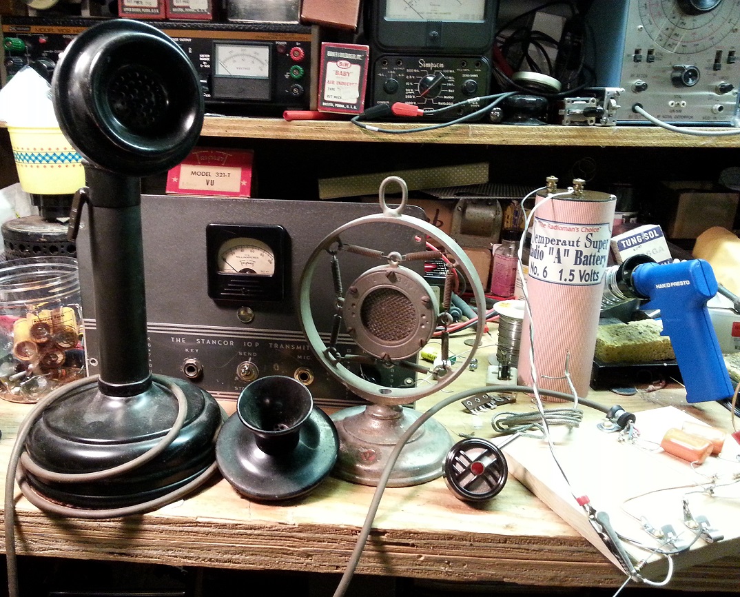
      Two are telephone-types, the T-32 (a pretty common desk mic around WW II) and an odd old telco one from the wood-wall and candlestick era next to it.  The Universal X1 in its nice stand was a complete surprise; I assumed from condition it was a goner.  Nope!  And the little Philmore lapel mic next to it had been sealed up.  The Stancor 10-P -- which needs a carbon mic to do AM -- is behind them.

     Here's my test set-up.  The mic cable goes to a little mixer.  It's isolated with 0.68 uF series condensers, looking at current across a 150 Ohm resistor in series with the mic, a 1.5 V battery and an added resistor to limit current -- I used 820 Ohms and it worked okay for checking.  In practice, you trim microphone current for best fidelity with a carbon -- usually the lower, the better, but there's a point where it stops working.
     Mic cable to mixer at left, connections to carbon mic under test at top right, battery terminals and added current-limiting resistor at bottom right.  I think you can trace it from the photo.

Thursday, March 26, 2015

STANCOR 10P TRANSMITTER: UPDATE 12

     A very long time in coming, I did make progress on the Stancor 10P, getting as far as power supply:

     Rectifier heaters and HV, filter caps, filter choke and bleeder.  It's a little crowded and I struggled to solder the capacitor and resistor to the chassis, even with the big iron.

     That work had it almost done, so tonight I added a few more things:
     Installed output feedthroughs and connected the output, wired up the primary power and the meter.

     Top view:

     Rear view:

     Front view:
     Initial tests -- just power-up, check for excessive current draw, check B+ -- went okay.  Hoping to try more by the weekend.

     Update: Tuned the transmitter up on 40m with a 100 Watt lamp in series, and it made a little power (4:1 balun to a Bird Wattmeter and 50 Ohm load.  Tried it without the lamp and blew the fuse instantly.  So....bigger fuse, and/or 150 and 200W lamps.  Maybe a little Amprobing..

     Update 25 May: Yesterday, I finally brought the transmitter up without a light bulb in series with the 120V AC and it worked. Last time I tried this with the wrong fuse (fast-blow) and it popped immediately -- at which point, I set the transmitter aside for awhile. I didn't have the balun and wattmeter for this test, just a 40W light bulb across the output, which is a bit low-resistance for the link coupling to match to. Plenty more to do but this was a big step.

Friday, November 15, 2013

W9BSP: A HAM'S HAM, A TEACHER'S TEACHER

     His name was Marshall H. Ensor.  He was a shop teacher in Olathe, Kansas; except for a stint traning radiomen during WW II, he spent most of his life there.  He spent it talking to the world and not just idle chatter, either -- Marshall Ensor (and his sister Loretta) spent evenings sending code practice and "teaching radio by radio," a free-for-the-listening lecture course over the powerful W9BSP - W9UA transmitter.
     I'd read all this in back issues of ARRL's magazine QST.  What I didn't know is the house where they lived is now a museum and the grounds around it are a park.  That big transmitter, in its fine-furniture cabinet, is back on the air again.

     As a shop teacher, he reached thousands.  There's no way to know how many people, all over the world, he taught about radio.  Tens of thousands?  (This modest man admitted in a resume sent to the U. S. Navy, "Reputed to have trained more radio operators than any other individual in the United States.") And all from a farmhouse in Kansas.

Thursday, October 10, 2013

STANCOR 10P TRANSMITTER: PART 10

     I made some impressive-looking progress this afternoon and stopped to photograph it because it's an example of a technique not everyone knows about: prewiring.
Photo is very large if you click on it
     There are a number of controls and jacks mounted on the front panel and it's a pretty tight fit.  Rather than mount them and try to get into a small space with needlenose pliers, soldering iron and solder, I wired up the most challenging (a multi-contact jack and a toggle switch) on the bench, and connected the input transformer to the microphone jack before installing it.

     This results in quite a few wires cut a little longer than necessary.  Yes, there will be some waste and yes, they sell that stuff by the foot, but how much does frustration cost?  By color-coding them, it it's easier to sort them out -- blue is plate return, red is B+, gray is cathode and switched ground, and black is ground, which are (mostly) old-time standard colors.

     The audio level control remains to be wired up and put in.  It mounts right in front of the rectifier tube, so lead dress will be important.  You can see the shielded lead from the mic transformer headed over to the empty hole in the front panel; another shielded wire will return from the control to the grid of the modulator tube.

     I had a bad moment when I realized I don't own a 1/2" Spintite driver to tighten the nuts of the 1/4" jacks.  But I do have a perfectly good modern Klein nutdriver that size.

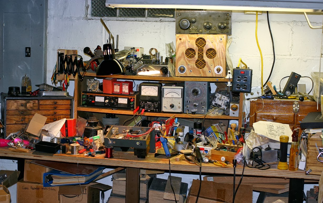
     My workbench is a little chaotic at present.
     As usual, tools have outstripped tool storage and projects have grown to take up the available space.  There's everything from the remains of an old soldering-iron control box and a balanced-line transmit-receive switch that didn't work out (not enough power supply for the relay!) to my QSL-40 transmitter, a box of pegboard hooks and big piece of un-etched PC board.  Somewhere over on the left is a jack box for the CW transmitters (half of them have the key jack on the back, some have heathen connectors that decent folk would never use instead of proper 1/4" two-circuit jacks) and a narrow audio filter.

Tuesday, July 23, 2013

JOHNSON VIKING CHALLENGER: INDY HAMFEST SWAG, PART FIVE

     E.F. Johnson built a wide range of amateur radio transmitters (among other things), starting in the 1920s.  They hit their stride with the postwar ham radio boom and continued through the early days of SSB.  Every last one of the postwar rigs was a "Viking" something-or-other, which I suppose isn't a huge surprise for a company based in Waseca MN, up there where the descendants of Vikings farmed the land.  The first two, delightful behemoths, were the Viking I and Viking II, but after that, there were Adventurers, Rangers, Navigators, Invaders(!) and the Challenger:
     There was one on a table at the Indy Hamfest, priced over $100 (a bit high, I thought) but the guy was starting to pack up and when he noticed my interest, suggested the price was highly negotiable.  I named a rather low one and he was okay with it -- even added a microphone.

     It's a CW/AM rig, the latter provided by screen-modulating a couple of TV sweep tubes (6DQ6) with a miniature beam tetrode audio tube (6AQ5).  One does not expect high fidelity from this kind of arrangement but given a decent load, it should be adequate.

     The knobs for bandswitch, "excitation" (grid drive) and mode switch are notably missing pointers to tell you where they're set.  The originals were sort of subtle, white plastic pieces glued in at the bottom of the knobs, and I'll have to work out a replacement.

     Does it work?  The seller claimed it did -- it's got Johnson's poorly-documented "push to talk" modification (no schematic, just a step-by-step and partial pictorial) and a connections-unknown mic socket, so I'll want to trace all that out first, clean it up and then, perhaps, power it up via The Gadget. 

     What's The Gadget?  That's a post for another time!

Sunday, May 19, 2013

DAYTON HAMVENTION 2013

     "Turk" Turon and I were at the Dayton Hamvention the better part of Friday and we saw about half.  It was amazing.  I passed up an early Globe transmitter -- next step smaller than the Globe King.  Shoulda, woulda--  Could not lift it.  Priced to move at $300 and in working condition.  Oh, if only!

    (I did manage a smaller/newer rig, a Heathkit DX-60, also said to be working.  We'll see.)

     Some rigs were way too big to move:
     Love that paint-job! (Here's a closer look.)
     This is the RF side; audio is the same size, with two more final-stage tubes and a nice window to enjoy them through.  Be sure to tune for minimum meltage.
     It's a Gates 1kW job, and very large for its size; but that just makes it easier to work on.  There was a Collins 20V in front of it, of which I hope to post pictures later.  Notice the bead-chain drive crossing the window?  The output tuning network is on the right side of the cabinet -- but Gates did't want all the knobs over there, that wouldn't be balanced!  So they extended it.  That means you'll be retuning a bit after start-up until cabinet temperature stabilizes: all that extra mechanical folderol carries a price.  The 20V has much the same trick, only with brass bead-chain, aluminum drive wheels and a steel cabinet, all mounted high up in a physically-smaller transmitter at the same power level, or, "Please touch up Loading adjustment once an hour until noon," as the note at one station read; they only ran the 20V one day a week and it woke slowly.

     Some hair was movingly big.
     Kristen had admirers wherever she went.

     Table of Vibroplexes.
     The new owner is just out of the shot.  Have I mentioned how good Vibroplex parts support is these days?  It is and you can thank him for it.

     Turk found a man-sized soldering copper.
     Well, more like statue-sized.  When they build the Radio Row monument in NYC, it'll be holding one of those, looking out at Lady Liberty as if wondering about asking to borrow the torch.

Tuesday, January 11, 2011

WE302

WE302? The standard desk phone. The 500-series phone that followed was just the same thing slicked-up for the sixties.

I've got one. If you call Roseholme Cottage (CLifford 3-....), that's what gets picked up. Blogger Keads has one, too -- with the original number card!

Treated well, a Western Electric 302 is nearly indestructible. Most phone systems will still accept pulse-dialing, too, and for the ones that don't, you can get magic pulse-to-touchtone widgets. The cloth cords can fray over time; Phoneco will sell you new ones, with all the proper lugs and anchors.

Saturday, March 27, 2010

THE PROPER WIRE

One of the frustrating parts of repairing older appliances is finding the right wire, especially power cord. Old ones very rarely survive in safe shape; most new ones look plain wrong.

For power cords, Sundial Wire has the answer. You've seen their work and haven't noticed it, in films and TV shows. They have very old-fashioned twisted-pair power cord...that just happens to be hiding modern insulation under the cloth.

Wiring up a classic radio or a telephone? Building retrotech from scratch? Check out the "Wire" listings under "Components" at Radio Daze; they have solid and stranded cloth-covered hookup wire in several sizes and many colors, including "pushback" solid, plus multiconductor cable and tinsel cord for telephone handsets, headphones and old-fashioned speakers. They have their own line of parallel-wire cloth-covered power cord and matching plugs, too.

Antique Electronics Supply has cloth-covered magnet wire in #24 and #26 size, plus Litz wire and cloth-covered hookup wire assortments, some power cord, cloth-type "spaghetti" insulating sleeving and #12 square tinned busbar.

Not Esoteric enough? Try the all-cotton-insulated wire at Jupiter Condenser Co. --And if you just have to have waxed-paper condensers, why, Jupiter's your only source of new ones, as far as I know. (The latter are not inexpensive but feature manufacturing techniques far superior to the old type; they've a line of modern Mylar fixed condensers as well). I have not done business with this company -- but they look interesting.

(Also stumbled over general-line/audiophile supplier Parts Connection, worth adding to your do-they-have-it? resources).

Monday, December 21, 2009

SAFETY REMINDER/PHONE UPDATE

Goggles: more than a fashion accessory.What reminded me was drilling into a concrete-block pillar in my basement to set anchors so I could mount the board that holds my steel "hotel" telephone. The chips do fly!

Look for an update soon as I have something more photogenic than a couple of 1x2 pine battens installed.

Friday, November 20, 2009

WHAT'S YOUR EXCHANGE?

In the early days of direct dialing, as 7-digit telephone numbers were adopted, Ma Bell decided people would never get used to remembering or dialing such a long string of numbers.

The solution was adopt exchange names for the first two digits; indeed, telephone exchanges were actual physical structures and they were generally referred to by that name. Even now, when the building (probably) houses an all-electronic digital switch instead of banks of electromechanical relays and crossbars, is not limited to a single pair of leading digits in the numbers it serves and may serve ten times as many subscribers, telephone company employees tend to call the locations the old prefix-names.

I knew a few -- Broad Ripple's exchange is CLifford and in WW II, Homeplace/Carmel numbers were VIctory, though I don't know if the exchange on 106th St. had been built at that time. I figured any master list(s) from the telephone companies were long gone.

"Long gone" is not so gone as you might think -- here's the 1955 list of Official Exchange names from AT&T! The Web's enabling of of information packrattery never ceases to amaze me.

UPDATE: Old Grouch points out the use of exchange names-as-numbers dates back at least to six-digit telephone numbers. See Comments

Wednesday, November 18, 2009

DIALTONE, DC AND RINGING: TELEPHONY

I have dialtone and DC on the hotel phone! Not only that, it rings, too, with a nice, distinctive note.

UPDATE: Wired the dial Thursday night. It works but has a little "dial tapping," meaning the bell jangles when the dial is in motion. I suspect this can be solved. It's a telephone!

Started out tonight (Wednesday) polishing the Bakelite front part of transmitter with Flitz (they didn't pay me, I'm just a happy customer) and proceeded to reassemble the entire transmitter: the "cup" or back is held to a nifty pivoting section by two screws through a washer, the "bulldog" style element is held to the cup by four tiny screws around its circumference; that subassembly is fastened to a socket on the front of the telephone with a hollow bolt, flat spring, bendy lockwasher and nut and at each step, you've got to thread the two wires from the element though the next part. It takes about as long to do as to describe and I had time left. H'mm, it's almost a (non-dial) telephone at this point. All it needs is the receiver.
(Note the fine old genuine Spintite nutdriver at the right. They don't make them like that any more, though a nice Klein set comes close*). The inside-the-phone part of the transmitter is at the left side of the upper section. The large silvery thing is the flat spring.

I wired up the receiver (tinsel cord, soft as a shoelace, very nice), connected Tip and Ring of the phone line cord to L1 and L2 terminals in the phone, plugged it in and there was dialtone, loud as life. Clicked the switchook (same as dialing "1") and I was left with DC talk voltage. Reached over to close the phone and it was obvious the transmitter worked, too. Wow! What's next?Talking to yourself, of course. I called my landline number from my celphone and the bell rang! The delay in a modern digital cell connection meant I could get a pretty good idea how the hotel phone sounds, too. It sounds just fine.

Next step is installing and connecting the dial. I have it in place now but I need to get the card in the center properly aligned. The dial is the tricky bit -- I can likely get it to dial but making it properly silence the receiver when it's off the rest position could be interesting.

So, for everyone who was wondering: yes. It definitely is a working telephone.
______________________________
* My Spintites are the best from a couple of sets. They used thinner steel than modern ones, which is nice for tight spots but wears out more quickly. Can't buy that kind new so you've got to find them used and evaluate them ruthlessly. This is an absolute affection; Xcelite, Vaco, Craftsman and Klein all make excellent nutdrivers and if the end result is what counts, you should buy a set by one of them. Worn drivers are nothing but trouble.

Monday, November 16, 2009

TELEPHONY, CONTINUED

Disassembled, cleaned, painted (lacquer!) and have begun, slowly, to reassemble the hotel phone. First, a collection of chassis parts -- the things in the center are the back of the transmitter (microphone) and the receiver (earpiece) hook: Basic assembly -- the front of the case is hinged to the back and I have test-fit the network, bell and hookswitch (less hook; it goes in later). Shown with a few of the tools used, including pen-type oiler at far left, used to put one drop of light oil on the hookswitch pivot (funny shading is the lighting, mild orange-peel texture is deliberate):No dial, receiver or transmitter yet. The latter is a whole collection of small parts, most of which I still have to clean and polish. Dial, hookswitch and receiver will be the very last parts fitted.

I did manage to remove and photocopy the schematic. Here's a black & white scan: Click for larger -- I have it larger still and in color for more detail, if anyone else is working on a Kellogg 1155-A or 1157-A telephone.

Friday, October 23, 2009

TELEPHONY IN THE HOME: A BEGINNING

It starts with this: I have new cloth-covered cordage for the incoming line and the receiver, a new receiver and a nicely-rebuilt dial. There's a network, bell, hookswitch and condenser inside the phone, condition unknown. Dirt appears to be the biggest issue. (That's a genuine Bell System screwdriver next to it, which fits the front panel screw that holds the phone closed like it was...made for it? Hey, how about that!) Step One, careful removal of the Inner Workings (with photos), followed by a little paint & body work.

Does anyone out there have any tips for removing the old schematic intact? Still glued in two spots. Distilled water on a cotton swab didn't help.