I made some impressive-looking progress this afternoon and stopped to photograph it because it's an example of a technique not everyone knows about: prewiring.
 |
| Photo is very large if you click on it |
There are a number of controls and jacks mounted on the front panel and it's a pretty tight fit. Rather than mount them and try to get into a small space with needlenose pliers, soldering iron and solder, I wired up the most challenging (a multi-contact jack and a toggle switch) on the bench, and connected the input transformer to the microphone jack before installing it.
This results in quite a few wires cut a little longer than necessary. Yes, there will be some waste and yes, they sell that stuff by the foot, but how much does frustration cost? By color-coding them, it it's easier to sort them out -- blue is plate return, red is B+, gray is cathode and switched ground, and black is ground, which are (mostly) old-time standard colors.
The audio level control remains to be wired up and put in. It mounts right in front of the rectifier tube, so lead dress will be important.
You can see the shielded lead from the mic transformer headed over to
the empty hole in the front panel; another shielded wire will return
from the control to the grid of the modulator tube.
I had a bad moment when I realized I don't own a 1/2" Spintite driver to tighten the nuts of the 1/4" jacks. But I do have a perfectly good modern Klein nutdriver that size.
My workbench is a little chaotic at present.
As usual, tools have outstripped tool storage and projects have grown to take up the available space. There's everything from the remains of an old soldering-iron control box and a balanced-line transmit-receive switch that didn't work out (not enough power supply for the relay!) to my QSL-40 transmitter, a box of pegboard hooks and big piece of un-etched PC board. Somewhere over on the left is a jack box for the CW transmitters (half of them have the key jack on the back, some have heathen connectors that decent folk would never use instead of proper 1/4" two-circuit jacks) and a narrow audio filter.


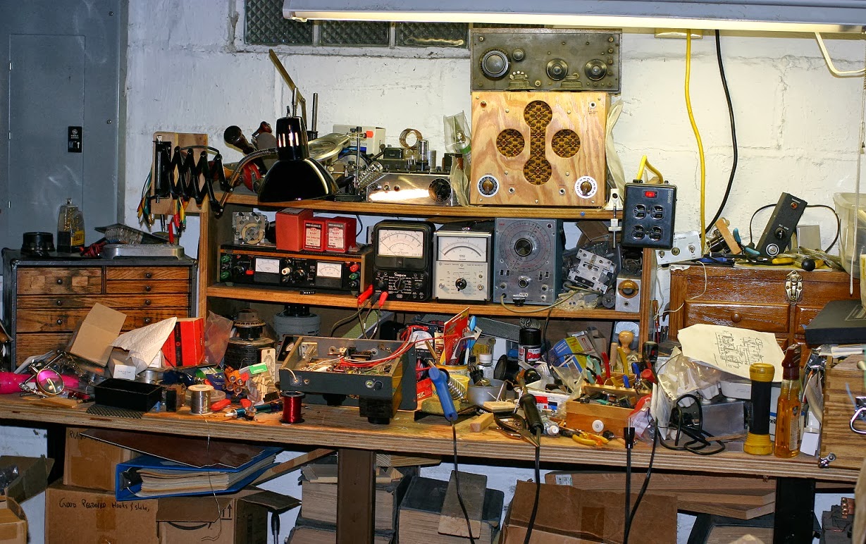


Is that a piece of B&K Precision gear to the left of the Simpson meter? The orange stripe on black looks familiar. We had a couple pieces of B&K in the lab when I was in vocational school. It wasn't much, but it was better than most of the EICO gear we had. We used to fight over the RCA VTVMs. Those things were almost indestructible.
ReplyDeleteYou're right about pre-wiring panel mounted controls and connectors. Even with (especially with) modern solid-state kits like the ones KI6DS sells, that fit in a case the size of a paperback novel.
Spotted! It's a variable power supply for tube gear, and for some reason the meter reads backwards. I really need to trace that out. (The price was right.) Anyway, variable 0-400V, 0-15- and fixed 6.3 and 12.6 V supplies.
ReplyDeleteYour workbench looks like mine - except mine is full of defunct Geiger counters, LNA's and other "stuff" I might need a part out of someday. Dave H. reminds me of the first Heathkit I ever assembled. I was spending most of my time in the electronics lab, with occasional breaks to listen to the war news from the "Land of Morning Mortars," and Pinky the Prof handed me a box and said "assemble this." It took about four hours, and the voltage check hit 1.6V on the head, and the ohmmeter tracked a very expensive General Radio resistance decade exactly. And it got me out of a dry as dust class on Mesopotamian dust.
ReplyDeleteThere were actually three major kit peddlers, with Heath Aircraft the best when properly assembled, Paco (Precision Apparatus Co out of Long Island) second - and the to--be-avoided--unless-there-was no choice EICO. Along with a number of specialty kit makers - which often wound up in the hands of kit bashers.
Which reminds me that when I was fresh married, I eked out my (respectable for the time) income building Johnson Rangers and Vikings at nite. And putting them on the air in the wee hours, during the legendary 1956 sunspot maxima. And yes, ten actually was open 24 hours a day for weeks on end. It took less than two weeks to work every DX entity beginning with "C" on the ITU list.
Stranger
As an extension of prewiring, perhaps the components could be installed on the panel "inside out" and wired there, then installed in their proper way. With due attention to orientation, of course.
ReplyDeleteRitchie, that's a great idea. I'll keep it in mind for my next kit. Thanks!
ReplyDeleteDepends on the panel and how likely it is to be scratched -- in a production environment, a "nailboard" for making wiring harnesses sometimes included a way to mount controls and connectors. A bit of tempered masonite could be drilled to match the panel, for instance, and either used to protect it or as a stand-alone support for assembling the wires and controls.
ReplyDeleteBe wary of mirror reversals. It is easier to do than you'd think.