His name was Marshall H. Ensor. He was a shop teacher in Olathe, Kansas; except for a stint traning radiomen during WW II, he spent most of his life there. He spent it talking to the world and not just idle chatter, either -- Marshall Ensor (and his sister Loretta) spent evenings sending code practice and "teaching radio by radio," a free-for-the-listening lecture course over the powerful W9BSP - W9UA transmitter.
I'd read all this in back issues of ARRL's magazine QST. What I didn't know is the house where they lived is now a museum and the grounds around it are a park. That big transmitter, in its fine-furniture cabinet, is back on the air again.
As a shop teacher, he reached thousands. There's no way to know how many people, all over the world, he taught about radio. Tens of thousands? (This modest man admitted in a resume sent to the U. S. Navy, "Reputed to have trained more radio operators than any other individual in the United States.") And all from a farmhouse in Kansas.
Showing posts with label TUBES. Show all posts
Friday, November 15, 2013
Tuesday, July 23, 2013
JOHNSON VIKING CHALLENGER: INDY HAMFEST SWAG, PART FIVE
E.F. Johnson built a wide range of amateur radio transmitters (among other things), starting in the 1920s. They hit their stride with the postwar ham radio boom and continued through the early days of SSB. Every last one of the postwar rigs was a "Viking" something-or-other, which I suppose isn't a huge surprise for a company based in Waseca MN, up there where the descendants of Vikings farmed the land. The first two, delightful behemoths, were the Viking I and Viking II, but after that, there were Adventurers, Rangers, Navigators, Invaders(!) and the Challenger:
There was one on a table at the Indy Hamfest, priced over $100 (a bit high, I thought) but the guy was starting to pack up and when he noticed my interest, suggested the price was highly negotiable. I named a rather low one and he was okay with it -- even added a microphone.
It's a CW/AM rig, the latter provided by screen-modulating a couple of TV sweep tubes (6DQ6) with a miniature beam tetrode audio tube (6AQ5). One does not expect high fidelity from this kind of arrangement but given a decent load, it should be adequate.
The knobs for bandswitch, "excitation" (grid drive) and mode switch are notably missing pointers to tell you where they're set. The originals were sort of subtle, white plastic pieces glued in at the bottom of the knobs, and I'll have to work out a replacement.
Does it work? The seller claimed it did -- it's got Johnson's poorly-documented "push to talk" modification (no schematic, just a step-by-step and partial pictorial) and a connections-unknown mic socket, so I'll want to trace all that out first, clean it up and then, perhaps, power it up via The Gadget.
What's The Gadget? That's a post for another time!
There was one on a table at the Indy Hamfest, priced over $100 (a bit high, I thought) but the guy was starting to pack up and when he noticed my interest, suggested the price was highly negotiable. I named a rather low one and he was okay with it -- even added a microphone.
It's a CW/AM rig, the latter provided by screen-modulating a couple of TV sweep tubes (6DQ6) with a miniature beam tetrode audio tube (6AQ5). One does not expect high fidelity from this kind of arrangement but given a decent load, it should be adequate.
The knobs for bandswitch, "excitation" (grid drive) and mode switch are notably missing pointers to tell you where they're set. The originals were sort of subtle, white plastic pieces glued in at the bottom of the knobs, and I'll have to work out a replacement.
Does it work? The seller claimed it did -- it's got Johnson's poorly-documented "push to talk" modification (no schematic, just a step-by-step and partial pictorial) and a connections-unknown mic socket, so I'll want to trace all that out first, clean it up and then, perhaps, power it up via The Gadget.
What's The Gadget? That's a post for another time!
Thursday, June 13, 2013
TUBE-TYPE MIC MIXER, PART 2
A reader complimented the schematic I posted yesterday. Of course, that's the "clean copy." Here's the one I drew as I traced it:
You will note several layout errors that are corrected in the later version -- don't know why I omitted the headphone jack wiring in that one, though. Schematic drawings can nearly always be improved after the first draft gets everything on paper (or on the screen, if you work that way). The rules are simple, applying them sometimes isn't.
And here's what I traced:
The Thordarson "Tru-Fidelity" mic transformers are not original -- the fellow who gave me the mixer salvaged the original UTC transformers. The Thordarsons are at least as good. They're also larger. I'm not happy with the length of unshielded wire in the grid leads, it will want changed. Looks like I took most of the wire harness lacing out when I traced it, too, so that needs redone as well. I wonder how those Sprague "Atoms" electrolytics are holding up? (They're on the terminal board behind the right-hand mic jack.)
Back panel:
Blank and ready for call letters! (It's traditional.)
2" Cannon connectors, with a penny for scale and ancient masking tape stuck on the chassis:
12-pin Jones plug, holes where a previous user had relocated the output terminals, fuseholder:
Rannie the cat loves my fancy screwdriver set:
This made disassembly a little more difficult.
(Here's another take on a small mic mixer, kind of interesting...if you have the parts.)
You will note several layout errors that are corrected in the later version -- don't know why I omitted the headphone jack wiring in that one, though. Schematic drawings can nearly always be improved after the first draft gets everything on paper (or on the screen, if you work that way). The rules are simple, applying them sometimes isn't.
And here's what I traced:
The Thordarson "Tru-Fidelity" mic transformers are not original -- the fellow who gave me the mixer salvaged the original UTC transformers. The Thordarsons are at least as good. They're also larger. I'm not happy with the length of unshielded wire in the grid leads, it will want changed. Looks like I took most of the wire harness lacing out when I traced it, too, so that needs redone as well. I wonder how those Sprague "Atoms" electrolytics are holding up? (They're on the terminal board behind the right-hand mic jack.)
Back panel:
Blank and ready for call letters! (It's traditional.)
2" Cannon connectors, with a penny for scale and ancient masking tape stuck on the chassis:
12-pin Jones plug, holes where a previous user had relocated the output terminals, fuseholder:
Rannie the cat loves my fancy screwdriver set:
This made disassembly a little more difficult.
(Here's another take on a small mic mixer, kind of interesting...if you have the parts.)
Wednesday, June 12, 2013
TUBE-TYPE MIC MIXER
It's been awhile since I traced the circuit and got it working:
Naturally, it was not working when I took it down from the shelf. Time to get out the signal tracer.
At some point before I got it, the front panel was covered in wood-grain laminate. I'm thinking a nice coat of plastic-friendly matte black would do it a world of good. And perhaps some RCA-type knobs that had not been painted, too.
(A word about the '2" Cannon' notation for the input connectors: that's what they are, great big old-fashioned microphone sockets. A mic-connector roundup post is in the works to provide examples.)
Naturally, it was not working when I took it down from the shelf. Time to get out the signal tracer.
At some point before I got it, the front panel was covered in wood-grain laminate. I'm thinking a nice coat of plastic-friendly matte black would do it a world of good. And perhaps some RCA-type knobs that had not been painted, too.
(A word about the '2" Cannon' notation for the input connectors: that's what they are, great big old-fashioned microphone sockets. A mic-connector roundup post is in the works to provide examples.)
Sunday, May 19, 2013
DAYTON HAMVENTION 2013
"Turk" Turon and I were at the Dayton Hamvention the better part of Friday and we saw about half. It was amazing. I passed up an early Globe transmitter -- next step smaller than the Globe King. Shoulda, woulda-- Could not lift it. Priced to move at $300 and in working condition. Oh, if only!
(I did manage a smaller/newer rig, a Heathkit DX-60, also said to be working. We'll see.)
Some rigs were way too big to move:
Love that paint-job! (Here's a closer look.)
This is the RF side; audio is the same size, with two more final-stage tubes and a nice window to enjoy them through. Be sure to tune for minimum meltage.
It's a Gates 1kW job, and very large for its size; but that just makes it easier to work on. There was a Collins 20V in front of it, of which I hope to post pictures later. Notice the bead-chain drive crossing the window? The output tuning network is on the right side of the cabinet -- but Gates did't want all the knobs over there, that wouldn't be balanced! So they extended it. That means you'll be retuning a bit after start-up until cabinet temperature stabilizes: all that extra mechanical folderol carries a price. The 20V has much the same trick, only with brass bead-chain, aluminum drive wheels and a steel cabinet, all mounted high up in a physically-smaller transmitter at the same power level, or, "Please touch up Loading adjustment once an hour until noon," as the note at one station read; they only ran the 20V one day a week and it woke slowly.
Some hair was movingly big.
Kristen had admirers wherever she went.
Table of Vibroplexes.
The new owner is just out of the shot. Have I mentioned how good Vibroplex parts support is these days? It is and you can thank him for it.
Turk found a man-sized soldering copper.
Well, more like statue-sized. When they build the Radio Row monument in NYC, it'll be holding one of those, looking out at Lady Liberty as if wondering about asking to borrow the torch.
(I did manage a smaller/newer rig, a Heathkit DX-60, also said to be working. We'll see.)
Some rigs were way too big to move:
Love that paint-job! (Here's a closer look.)
This is the RF side; audio is the same size, with two more final-stage tubes and a nice window to enjoy them through. Be sure to tune for minimum meltage.
It's a Gates 1kW job, and very large for its size; but that just makes it easier to work on. There was a Collins 20V in front of it, of which I hope to post pictures later. Notice the bead-chain drive crossing the window? The output tuning network is on the right side of the cabinet -- but Gates did't want all the knobs over there, that wouldn't be balanced! So they extended it. That means you'll be retuning a bit after start-up until cabinet temperature stabilizes: all that extra mechanical folderol carries a price. The 20V has much the same trick, only with brass bead-chain, aluminum drive wheels and a steel cabinet, all mounted high up in a physically-smaller transmitter at the same power level, or, "Please touch up Loading adjustment once an hour until noon," as the note at one station read; they only ran the 20V one day a week and it woke slowly.
Some hair was movingly big.
Kristen had admirers wherever she went.
Table of Vibroplexes.
The new owner is just out of the shot. Have I mentioned how good Vibroplex parts support is these days? It is and you can thank him for it.
Turk found a man-sized soldering copper.
Well, more like statue-sized. When they build the Radio Row monument in NYC, it'll be holding one of those, looking out at Lady Liberty as if wondering about asking to borrow the torch.
Saturday, February 23, 2013
THE NATIONAL COMPANY'S SRR RECEIVER
The acronym stands for "Super Regenerative Receiver" and I think it was their first foray into the old amateur radio 5 meter band, before the sophisticated 1-10 "Ultra High frequency" receiver was much more than a gleam in James Millen's eye.
It's a tiny thing, 7¾" x 7¾" x 7" and 5 meters is where it tops out; with a minor reshuffling of coil connections, it covers the lower ham bands, from 10 meters down to 160 meters.
As a "rushbox" super-regen without an RF amplifier to isolate the detector from the antenna, it's not a good citizen on any of them; in operation, it radiates a broad swath of noise, inherent in the superregeneration process.*
And I own one. There it was, at the Indiana Historical Radio Society's Spring swapmeet, standing out on a seller's table to anyone with an eye for old National equipment, at a remarkably low price. I made an offer and somehow ended up with a nice homebrew absorption wavemeter in the bargain.
Have a look inside the receiver:
The coil and socket are standard 4-pin "tube base" configuration, unusual for a National product; they usually preferred their own designs. But that will make it simpler to wind new coils. The one in the socket probably isn't for this receiver -- not just the "Hammarlund" name on it, it lacks the cathode tap found on all SRR coils. I may have coil-winding data. I'm certainly going to give it a try!
Rough schematic:
It uses a version of National's "S-101" interstage coupler that I had not seen before. The S-101 is a weak point in the design, as the internal audio choke (inductor) has a very high impedance, meaning many turns of small-gauge wire, which tends to perish in the potting compound. Checking that will be the first order of business.
_________________________________
* I believe it was Howard Hughes' 1938 around-the-world flight that found radio communication nearly wiped out by interference from people trying to listen in with simple superregenerative receivers. This is why the later 1-10 had an RF amp, to keep that detector from getting in the way!
It's a tiny thing, 7¾" x 7¾" x 7" and 5 meters is where it tops out; with a minor reshuffling of coil connections, it covers the lower ham bands, from 10 meters down to 160 meters.
As a "rushbox" super-regen without an RF amplifier to isolate the detector from the antenna, it's not a good citizen on any of them; in operation, it radiates a broad swath of noise, inherent in the superregeneration process.*
And I own one. There it was, at the Indiana Historical Radio Society's Spring swapmeet, standing out on a seller's table to anyone with an eye for old National equipment, at a remarkably low price. I made an offer and somehow ended up with a nice homebrew absorption wavemeter in the bargain.
Have a look inside the receiver:
The coil and socket are standard 4-pin "tube base" configuration, unusual for a National product; they usually preferred their own designs. But that will make it simpler to wind new coils. The one in the socket probably isn't for this receiver -- not just the "Hammarlund" name on it, it lacks the cathode tap found on all SRR coils. I may have coil-winding data. I'm certainly going to give it a try!
Rough schematic:
It uses a version of National's "S-101" interstage coupler that I had not seen before. The S-101 is a weak point in the design, as the internal audio choke (inductor) has a very high impedance, meaning many turns of small-gauge wire, which tends to perish in the potting compound. Checking that will be the first order of business.
_________________________________
* I believe it was Howard Hughes' 1938 around-the-world flight that found radio communication nearly wiped out by interference from people trying to listen in with simple superregenerative receivers. This is why the later 1-10 had an RF amp, to keep that detector from getting in the way!
Sunday, February 17, 2013
NEW TUBE TRANSMITTER KIT
Yes, there's a new one: Chinese kit-maker YouKits offers their TT1A two-tube transmitter kit for US$129, less power transformer, HV rectifier and filter (though they supply all the info to build the B+ supply).
It's a nice-looking little kit, with a tube lineup that appears to be close to 6C4 - 6AQ5. The instruction manual is very clear, which solves the main concern of internationally-marketed kits. Have no fear, YouKits has found someone bilingual in Ham.
They also offer more-modern kits and an impressive antenna analyzer that is also sold in the U.S. by Ten-Tec.
It's a nice-looking little kit, with a tube lineup that appears to be close to 6C4 - 6AQ5. The instruction manual is very clear, which solves the main concern of internationally-marketed kits. Have no fear, YouKits has found someone bilingual in Ham.
They also offer more-modern kits and an impressive antenna analyzer that is also sold in the U.S. by Ten-Tec.
Friday, October 5, 2012
FLIP, FLOP AND...FLOWCHART?
In honor of Tam's link from a post showing examples of logic elements from early computers, here's a link to a site showing a nice dual-triode flip-flop as used in the Burroughs 205. (Plus actual pictures of actual hardware.) Enough of those and you'd have yourself some memory; also an air-conditioning challenge. But wouldn't it be fun?
Labels:
TUBES
Thursday, August 30, 2012
VACUUM-TUBE COMEBACK?
And in computers, yet? That's the report, though they're not going to look very much like the 6SN7s in Grandpa's flip-flops; nuvistors would look like skyscrapers beside them. Still and all, tubes. Who would've thought?
Labels:
TUBES
Sunday, July 22, 2012
CALLSIGN NABD, USS INDIANAPOLIS, CA-35
She was torpedoed in the Pacific 30 July, 1945, after delivering an atom bomb to Tinian. Of 1,196 crew, some 900 made it into the shark-infested water. Despite sending a distress call, the sinking went unnoticed for five days. Only 317 men survived. It remains one of the worst U. S. naval disasters.
The USS Indianapolis Memorial is here in Indianapolis, and a room of the Indiana War Memorial Museum is dedicated to the ship. Just around the corner in the War Memorial, volunteers have recreated the ship's "Radio Central," piece by piece.
11 of the 41 radiomen were among the survivors.
The original installation is gone with the ship, but the equipment was quite standardized. "Was" being the operational word, as much of it has become quite scarce. The old receivers were uncommonly good -- and uncommonly heavy; the transmitters were even more so, on both counts.
So simply collecting the equipment is a huge accomplishment. But the volunteers are committed to more than mere static display -- they're getting the old gear running!
Entry is very much like stepping into a busy radio room -- CW in the background (including "SOS SOS de NABD...") and recorded talk about the gear plays at several positions.
Visitors walk down a narrow aisle between transmitters and the test bench before coming to the row of operating positions. Left:
Center:
Right:
Ship's radio rooms are a pretty fair match for the ideal ham shack, too, though I don't suppose very many of the guys copy traffic on a "mill" these days. (And I wonder if there might not be a few southpaws on the crew -- or did the Navy train ops to send left-handed?)
The transmitters cover from low frequencies all the way into VHF, with "big rigs" into the upper HF range.
The big transmitters are right there where you can get a good look.
The TBS low VHF transmitter-receiver they've been getting into operating condition is kept far enough away to keep curious fingers safe. You can just see the side of it in the right-side image of the operating positions -- the acronym for this is sometimes (and unofficially) translated "Talk Between Ships" and sure enough, my Dad's 1946 Introduction to Radio Equipment, NAVPERS 10172* says it was "designed to provide short-range communications between surface craft such as task forces or convoys." Interestingly, the book covers operation of just about every receiver and transmitter in the USS Indianapolis Radio Room exhibit.
It's a fascinating installation. It includes a couple of Amateur Radio operating positions, at the Supervisor and Test desks, operating as WW2IND:
The more modern ham gear is kept out of sight when not in use, but pipe that shiny green SP-600! I'll be back -- the museum is not very far from where I work and they tell me volunteers are present many mornings and all day most Thursdays.
________________________________
* This book was my first exposure to the technical side of radio, and does a pretty good job of covering basic theory before moving on to specific equipment. The Naval Reserve, when they learned my father worked for RCA, was determined to make him a radioman...until realizing he didn't know International Morse code. Rather than run a reservist through radio-op school, they set him to toting bags of powder in a gun turret. Which is, if you ask me, one more reason to learn CW! Why'd they think Dad would be a radioman? Have a close look at the photos and you'll see a discreet RCA "meatball" on an awful lot of Navy comms gear; RCA and radio were just about synonyms, as far as the Navy was concerned. There are only two non-RCA receivers on the entire NABD operating bench shown above, in fact -- can you ID them?
The USS Indianapolis Memorial is here in Indianapolis, and a room of the Indiana War Memorial Museum is dedicated to the ship. Just around the corner in the War Memorial, volunteers have recreated the ship's "Radio Central," piece by piece.
11 of the 41 radiomen were among the survivors.
The original installation is gone with the ship, but the equipment was quite standardized. "Was" being the operational word, as much of it has become quite scarce. The old receivers were uncommonly good -- and uncommonly heavy; the transmitters were even more so, on both counts.
So simply collecting the equipment is a huge accomplishment. But the volunteers are committed to more than mere static display -- they're getting the old gear running!
Entry is very much like stepping into a busy radio room -- CW in the background (including "SOS SOS de NABD...") and recorded talk about the gear plays at several positions.
The transmitters cover from low frequencies all the way into VHF, with "big rigs" into the upper HF range.
It's a fascinating installation. It includes a couple of Amateur Radio operating positions, at the Supervisor and Test desks, operating as WW2IND:
________________________________
* This book was my first exposure to the technical side of radio, and does a pretty good job of covering basic theory before moving on to specific equipment. The Naval Reserve, when they learned my father worked for RCA, was determined to make him a radioman...until realizing he didn't know International Morse code. Rather than run a reservist through radio-op school, they set him to toting bags of powder in a gun turret. Which is, if you ask me, one more reason to learn CW! Why'd they think Dad would be a radioman? Have a close look at the photos and you'll see a discreet RCA "meatball" on an awful lot of Navy comms gear; RCA and radio were just about synonyms, as far as the Navy was concerned. There are only two non-RCA receivers on the entire NABD operating bench shown above, in fact -- can you ID them?
Saturday, May 19, 2012
DAYTON HAMVENTION, 2012
One commercial vendor offered miniature straight keys, J-38ish (the general Bunnell "Triumph" pattern, widely used in the U.S.) but about 3/8 full size. I wanted one...but didn't buy one on sight and, of course, could not find them again.
But that was all I missed at Dayton. I didn't buy anything large, but several smaller items came home with me along with plenty of photographs.
Among my purchases: a couple of books from the RSGB, the previously-mentioned Varispeeds (and a contact burnisher: I nearly lost a QSO two days ago thanks to dirty key contacts!), a pair of 6BG6 tubes, a kind of an octal 807 beam power tube, some round "Ohmite" type knobs, an NOS Hammarlund plug-in coil form in the original box, ceramic standoff insulators and a National variable condenser.
And that's a glimpse of my day at the Hamvention. I'm thinking about driving back Sunday -- need to top up the oil in my car, first.
Sunday, April 15, 2012
JOHN HUNTOON'S RECEIVER
Built from an article he wrote for Radio (not QST!) as a young adult. I'll scan it in later.
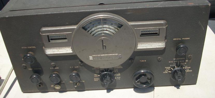
Here's the front panel, bandset condenser at the upper left on the side, bandspread tuning via the National type B dial, regeneration at lower left and on-off at lower right:
I had to build the chassis. It's just galvanized sheet metal -- aluminum might look nicer. Top view with the lid off -- band selection by plug-in coils! I didn't have any simple-type grid-cap clips but the little brass coil spring works okay:
From below, you can see my efforts to "fine tune" the regeneration control with paralleled resistors. The original used a carbon-compression rheostat, an early multi-turn variable resistance, but I had to come up with a coarse setting:
Multiwire cable out the back to the batteries -- 3V "A" and a 45V, tapped at 22.5V "B." The detector is a type '32 screen-grid tube with two stages of audio from the '19 dual-triode in the back compartment.
LATER: Here are the scans, of the photocopies I worked from back when I built it. I don't seem to have the first page and there's about a decade (110 issues) of RADIO to go through, so gimme a few. I used a different bandset condenser, detector plate audio-coupling choke and RFC -- his looks to be a Hammarlund.

Here's the front panel, bandset condenser at the upper left on the side, bandspread tuning via the National type B dial, regeneration at lower left and on-off at lower right:
LATER: Here are the scans, of the photocopies I worked from back when I built it. I don't seem to have the first page and there's about a decade (110 issues) of RADIO to go through, so gimme a few. I used a different bandset condenser, detector plate audio-coupling choke and RFC -- his looks to be a Hammarlund.


Monday, August 16, 2010
RCA HAM TIPS
Scanned in and available online thanks to a kindly ham (N4TRB), a nice collection of "RCA Ham Tips" from the 1930s onwards. These were little flyers featuring a single project using RCA tubes (or later, transistors), nicely built and written up by genuine RCA engineers, usually amateur radio operators themselves. Most are as buildable now as they were when new, and every bit as much fun.
Labels:
IN THE WORKSHOP,
RADIO,
TUBES
Friday, April 23, 2010
INDIANA HISTORICAL RADIO SOCIETY SPRING MEET
It's next weekend! The IHRS Spring Meet: April 30 - May 1, 2010 at the Kokomo Event Center, located at 1500 North Reed Road (US 31) in (where else) Kokomo, IN. Friday April 30 - 4:00 pm to 8:00 pm; Saturday May 1 - 7:00 am to 2:00 pm. Plenty of indoor Radio Swap and Sell space. Vintage radio contests. Radio operation and repair seminars.
Fees -- General admission is free. One Swap N Sell space for the sale and trade of vintage radio equipment is $15.00 for IHRS members, $20.00 for non-members, good for both days (the space includes one eight foot table.)
I have missed the last couple of IHRS meetings. The Winter one was cancelled by a snowstorm! So I'm really hoping to get to this one.
Fees -- General admission is free. One Swap N Sell space for the sale and trade of vintage radio equipment is $15.00 for IHRS members, $20.00 for non-members, good for both days (the space includes one eight foot table.)
I have missed the last couple of IHRS meetings. The Winter one was cancelled by a snowstorm! So I'm really hoping to get to this one.
Monday, October 19, 2009
TUBE REBUILDERS
Ever see a power tube getting rebuilt? Didja know it could be done? One of my favorite tube rebuilders, Kennetron, has a bit of a virtual tour of their plant!
Sure, there are other rebuilders; many years ago, I used Econco for big Class C power tubes in FM service (now a wholly-owned division of CPI, which also owns Eimac, it looks like they have dropped their old, irreverent "use a transistor, go to jail" tagline) and I've always heard good things about Freeland Products. Still, I have a soft spot for Kennetron, who have so far been the only outfit willing to take on rebuilding small (1000 Watt!) ceramic external-anode power tetrodes used at ultra high frequencies in Class AB1 -- and their rebuilds work! This is a fussy task, combining the skills of jeweler, machinist, welder and more for devices that operate in about the same power range as chainsaws.
It's a heck of a thing to send in old, worn-out, even shorted "empties" and get 'em back at half the price or less of new tubes, ready to go.
Power tube rebuilders are a scarce breed. The collection of skills and equipment to do the job, from vacuum engineering to glass building to fabricating the intricate internal assemblies, is rare and unlikely -- we're lucky there are at least three left!
Sure, there are other rebuilders; many years ago, I used Econco for big Class C power tubes in FM service (now a wholly-owned division of CPI, which also owns Eimac, it looks like they have dropped their old, irreverent "use a transistor, go to jail" tagline) and I've always heard good things about Freeland Products. Still, I have a soft spot for Kennetron, who have so far been the only outfit willing to take on rebuilding small (1000 Watt!) ceramic external-anode power tetrodes used at ultra high frequencies in Class AB1 -- and their rebuilds work! This is a fussy task, combining the skills of jeweler, machinist, welder and more for devices that operate in about the same power range as chainsaws.
It's a heck of a thing to send in old, worn-out, even shorted "empties" and get 'em back at half the price or less of new tubes, ready to go.
Power tube rebuilders are a scarce breed. The collection of skills and equipment to do the job, from vacuum engineering to glass building to fabricating the intricate internal assemblies, is rare and unlikely -- we're lucky there are at least three left!
Subscribe to:
Posts (Atom)


